- 您現(xiàn)在的位置:買賣IC網(wǎng) > PDF目錄383055 > GS9025A (Electronic Theatre Controls, Inc.) Serial Digital Receiver PDF資料下載
參數(shù)資料
| 型號(hào): | GS9025A |
| 廠商: | Electronic Theatre Controls, Inc. |
| 英文描述: | Serial Digital Receiver |
| 中文描述: | 串行數(shù)字接收機(jī) |
| 文件頁(yè)數(shù): | 15/18頁(yè) |
| 文件大小: | 192K |
| 代理商: | GS9025A |
第1頁(yè)第2頁(yè)第3頁(yè)第4頁(yè)第5頁(yè)第6頁(yè)第7頁(yè)第8頁(yè)第9頁(yè)第10頁(yè)第11頁(yè)第12頁(yè)第13頁(yè)第14頁(yè)當(dāng)前第15頁(yè)第16頁(yè)第17頁(yè)第18頁(yè)
GENNUM CORPORATION
522 - 75 - 00
15
G
This causes lift in the transfer function given by:
To keep peaking to less than 0.05dB:
w
Z
< 0.0057w
BW
9.3 Selection of Loop Filter Components
Based on the above analysis, the loop filter components
should be selected for a given PLL bandwidth,
3dB
, as
follows:
1. Calculate
where:
I
CP
is the charge pump current and is a function of the
R
VCO
resistor and is obtained from Figure 24.
K
= 90MHz/V for VCO frequencies corresponding to
the
L
curve.
K
= 140MHz/V for VCO frequencies corresponding to
the
H
curve.
N is the divider modulus
(
L
,
H
and N can be obtained from Table 2 or Table 3)
2. Choose R
LF
= 2(3.14)
3dB
(0.78)L
3. Choose C
LF1
= 174L/(R
LF
)
2
4. Choose C
LF2
= L/4(R
LF
)
2
Fig. 24 R
VCO
vs. Charge Pump Current
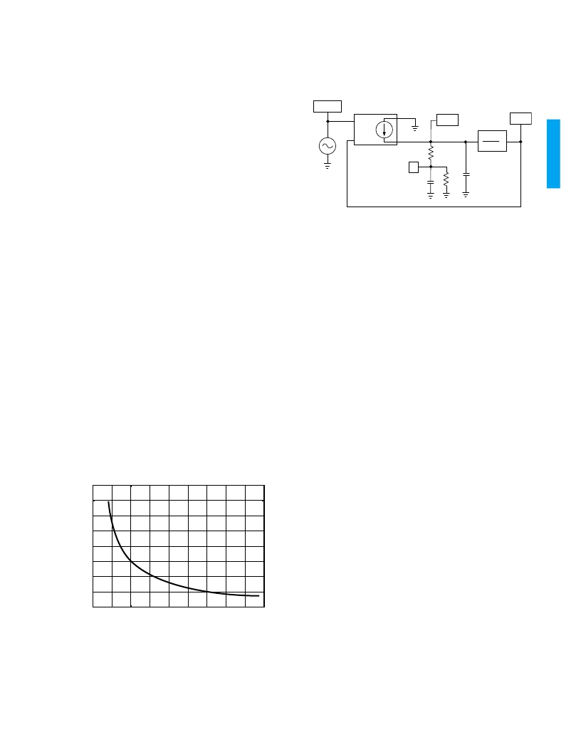
9-4. SPICE Simulations
More detailed analysis of the GS9025A PLL can be done
using SPICE. A SPICE model of the PLL is shown below:
Fig. 25 SPICE Model of the PLL
The model consists of a voltage controlled current source
(G1), the loop filter components (R
LF
, C
LF1
, and C
LF2
), a
voltage controlled voltage source (E1), and a voltage
source (V1). R2 is necessary to create a DC path to ground
for Node 1.
V1 is used to generate the input phase waveform. G1
compares the input and output phase waveforms and
generates the charge pump current,
Ι
CP
. The loop filter
components integrate the charge pump current to establish
the loop filter voltage. E1 creates the output phase
waveform (PHIO) by multiplying the loop filter voltage by
the value of the Laplace transform (2
π
K
/Ns).
The net list for the model is given below. The .PARAM
statements are used to set values for
Ι
CP
, K
, N, and D.
Ι
CP
is determined by the R
VCO
resistor and is obtained from
Figure 24.
SPICE NETLIST * GS9025A PLL Model
.PARAM ICP = 165E-6 KF= 90E+6
.PARAM N = 1 D = 0.5
.PARAM PI = 3.14
.IC V(Phio) = 0
.ac dec 30 1k 10meg
RLF 1 LF 1000
CLF1 1 0 15n
CLF2 0 LF 15p
E_LAPLACE1 Phio 0 LAPLACE {V(LF)} {(2*PI*KF)/(N*s)}
G1 0 LF VALUE{D * ICP/(2*pi)*V(Phii, Phio)}
V1 2 0 DC 0V AC 1V
R2 0 1 1g
.END
20 LOGw
w
Z
---------
20 LOG
1
w
BW
-----------
–
---------------------
=
L
I
CP
K
---------------
=
0
50
100
150
200
250
300
350
400
0
200
400
600
800
1000
1200
1400
1600
1800
C
R
VCO
(
)
PHII
PHIO
R2
E1
R
LF
C
LF1
C
LF2
G1
V1
2
π
K
Ns
IN+
IN-
1
LF
NOTE: PHII, PHIO, LF, and 1 are node names in the SPICE netlist.
相關(guān)PDF資料 |
PDF描述 |
|---|---|
| GS9025ACQM | Serial Digital Receiver |
| GS9025ACTM | Serial Digital Receiver |
| GS9028 | Cable Driver with Two Adjustable Outputs |
| GS9028-CKA | Cable Driver with Two Adjustable Outputs |
| GS9028-CTA | Cable Driver with Two Adjustable Outputs |
相關(guān)代理商/技術(shù)參數(shù) |
參數(shù)描述 |
|---|---|
| GS9025A_05 | 制造商:GENNUM 制造商全稱:GENNUM 功能描述:Serial Digital Receiver |
| GS9025ACQM | 制造商:Rochester Electronics LLC 功能描述: 制造商:Gennum Corporation 功能描述: |
| GS9025ACQME3 | 制造商:Semtech Corporation 功能描述:Cable Equalization 44-Pin MQFP Tray 制造商:Semtech Corporation 功能描述:GS9025 Series 540 Mb/s Cable Equalization Serial Digital Receiver - MQFP-44 制造商:Semtech Corporation 功能描述:Receiver |
| GS9025ACTM | 制造商:GENNUM 制造商全稱:GENNUM 功能描述:Serial Digital Receiver |
| GS9025ACTME3 | 制造商:Semtech Corporation 功能描述:Receiver |
發(fā)布緊急采購(gòu),3分鐘左右您將得到回復(fù)。