- 您現(xiàn)在的位置:買賣IC網(wǎng) > PDF目錄370342 > GM72V28841ALT-8 x8 SDRAM PDF資料下載
參數(shù)資料
| 型號: | GM72V28841ALT-8 |
| 英文描述: | x8 SDRAM |
| 中文描述: | x8 SDRAM內(nèi)存 |
| 文件頁數(shù): | 8/10頁 |
| 文件大?。?/td> | 81K |
| 代理商: | GM72V28841ALT-8 |

GM72V66441ET/ELT
Rev. 1.1/Apr.01
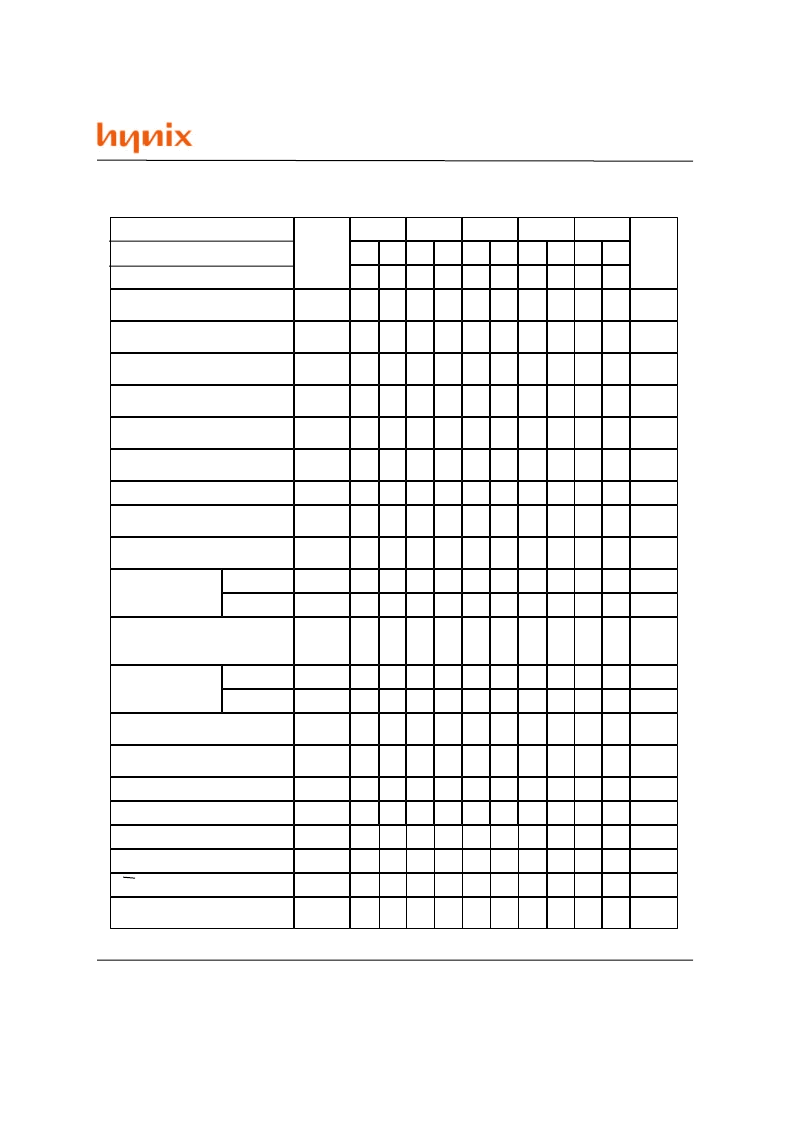
Relationship Between Frequency and Minimum Latency
Notes
l
RCD
1
Active command to column
command (same bank)
Active command to active
command (same bank)
Active command to Precharge
command (same bank)
Precharge command to active
command (same bank)
Write recovery or last data-in to
Precharge command
(same bank)
Active command to active
command (different bank)
Self refresh exit time
Last data in to active command
(Auto Precharge, same bank)
Self refresh exit to command
input
Precharge
command to
high impedance
Last data out to active
command
(auto Precharge) (same bank)
Last data out to
Precharge
(early Precharge)
Column command to column
command
Write command to data in
latency
DQM to data in
l
RC
= [
l
RAS
+
l
RP
], 1
l
RAS
l
RP
1
l
RWL
1
l
RRD
1
l
SREX
l
APW
= [
l
RWL
+
l
RP
], 1
l
SEC
= [
l
RC
]
l
HZP
l
HZP
(CL=2)
(CL=3)
l
APR
l
EP
l
EP
(CL=2)
(CL=3)
l
CCD
l
WCD
l
DID
l
DOD
l
CLE
l
RSA
l
CDD
DQM to data out
l
PEC
Power down exit to command
input
CKE to CLK disable
Register set to active command
Parameter
t
CK
(ns)
frequency(MHz)
1
CS to command disable
Symbol
-7J
100
2
7
5
10
2
1
2
1
3
7
-
3
1
-
- 2
1
0
0
2
1
1
1
0
-75
133
3
9
6
7.5
3
1
2
1
4
9
-
3
1
-
-2
1
0
0
2
1
1
1
0
-8
125
3
9
6
8
3
1
2
1
4
9
-
3
1
-
-2
1
0
0
2
1
1
1
0
100
2
7
5
10
2
1
2
2
3
7
2
3
1
-1
-2
1
0
0
2
1
1
1
0
66
2
6
4
15
2
1
2
2
3
6
2
3
1
-1
- 2
1
0
0
2
1
1
1
0
-7
143
3
9
6
7
3
1
2
1
4
9
-
3
1
-
-2
1
0
0
2
1
1
1
0
100
2
7
5
10
2
1
2
1
3
7
2
3
1
- 1
- 2
1
0
0
2
1
1
1
0
-7K
100
2
7
5
10
2
1
2
1
3
7
2
3
1
-1
-2
1
0
0
2
1
1
1
0
100
2
7
5
10
2
1
2
1
3
7
2
3
1
-1
-2
1
0
0
2
1
1
1
0
100
2
7
5
10
2
1
2
1
3
7
2
3
1
- 1
- 2
1
0
0
2
1
1
1
0
-8-
相關(guān)PDF資料 |
PDF描述 |
|---|---|
| GM72V28841AT-10K | x8 SDRAM |
| GM72V28841AT-75 | x8 SDRAM |
| GM72V28841AT-7J | x8 SDRAM |
| GM72V28841AT-7K | x8 SDRAM |
| GM72V28841AT-8 | x8 SDRAM |
相關(guān)代理商/技術(shù)參數(shù) |
參數(shù)描述 |
|---|---|
| GM72V28841AT-10K | 制造商:未知廠家 制造商全稱:未知廠家 功能描述:x8 SDRAM |
| GM72V28841AT-75 | 制造商:未知廠家 制造商全稱:未知廠家 功能描述:x8 SDRAM |
| GM72V28841AT-7J | 制造商:未知廠家 制造商全稱:未知廠家 功能描述:x8 SDRAM |
| GM72V28841AT-7K | 制造商:未知廠家 制造商全稱:未知廠家 功能描述:x8 SDRAM |
| GM72V28841AT-8 | 制造商:未知廠家 制造商全稱:未知廠家 功能描述:x8 SDRAM |
發(fā)布緊急采購,3分鐘左右您將得到回復(fù)。