- 您現(xiàn)在的位置:買賣IC網(wǎng) > PDF目錄64980 > GM6156-2.5ST25R (American Power Management Inc.) 150mA LOW-NOISE LDO REGULATOR PDF資料下載
參數(shù)資料
| 型號: | GM6156-2.5ST25R |
| 廠商: | American Power Management Inc. |
| 英文描述: | 150mA LOW-NOISE LDO REGULATOR |
| 中文描述: | 150mA低噪聲LDO穩(wěn)壓器 |
| 文件頁數(shù): | 6/9頁 |
| 文件大小: | 126K |
| 代理商: | GM6156-2.5ST25R |
G
M
6
1
5
6
The actual power dissipation of the regulator circuit can be determined using by the equation:
P
= (V
- V
) I
+ V
I
D
IN
OUT
IN GND
Substituting P
for P
and solving for the operating conditions that are critical to the application will give
D(max)
D
the maximum operating conditions for the regulator circuit. For example, when operating the GM6156 at room
temperature with a minimum footprint layout, the maximum input voltage for a set output current can be
determined as follows:
The junction-to-ambient thermal resistance for the minimum footprint is 220°C/ W, from Table 1. The maximum
power dissipation must not be exceeded for proper operation. Using the output voltage of 3.3V and an output
current of 150mA, the maximum input voltage can be determined. From the Electrical Characteristics table, the
maximum ground current for150mA output current is 2500 or 2.5mA.
455mW = (V
- 3.3V) 150mA + V
2.5mA
IN
455mW = V
150mA - 495mA + V
2.5mA
IN
950mW = V
152.5mA
IN
V
= 6.23V
IN(max)
Therefore, a 3.3V application at 150mA of output current can accept a maximum input voltage of 6.2V in a
SOT-25 package. For a full discussion of heat sinking and thermal effects on voltage regulators.
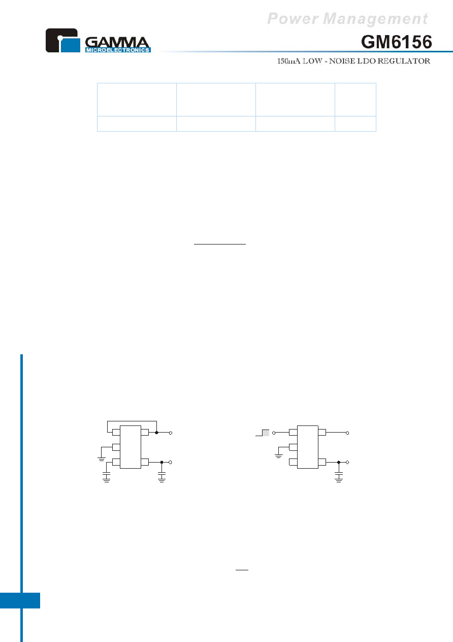
Fixed Regulator Applications
Figure 3. Ultra-Low-Noise Fixed Voltage Application
Figure 4. Low-Noise Fixed Voltage Application
Adjustable Regulator Applications
The GM6156 can be adjusted to a specific output voltage by using two externa resistors (Figure 5). The resistors set the
output voltage based on the following equation:
P
=
D(max)
P
= 455mW
D(max)
(125°C - 25°C)
220°C/W
Figure3 includes a 470pF capacitor for low-noise
operation and shows EN (pin 3) connected to IN (pin 1)
for an application where enable/ shutdown is not
required. C
= 2.2F minimum.
OUT
G
M
6
1
5
6
1
2
3
4
5
VIN
VOUT
2.2F
470pF
Enable
Shutdown
Figure 4 is an example of a low-noise configuration
where C
is not required. C
= 1F minimum.
BYP
OUT
V
= 1.242V X (
+1)
OUT
R2
R1
Parameter
R
Recommended
JA
q
Minimum Footprint
R
1" Square
JA
q
Copper Clad
R JC
q
SOT-23-5
220°C/ W
170°C/ W
130°C/ W
Table 1. SOT-25 Thermal Resistance
G
M
6
1
5
6
1
2
3
4
5
VIN
VOUT
1.0F
EN
BYP
相關(guān)PDF資料 |
PDF描述 |
|---|---|
| GM6156-2.7ST25R | 150mA LOW-NOISE LDO REGULATOR |
| GM6156-2.8ST25R | 150mA LOW-NOISE LDO REGULATOR |
| GM6156-3.0ST25R | 150mA LOW-NOISE LDO REGULATOR |
| GM6156-3.3ST25R | 150mA LOW-NOISE LDO REGULATOR |
| GM6156-3.6ST25R | 150mA LOW-NOISE LDO REGULATOR |
相關(guān)代理商/技術(shù)參數(shù) |
參數(shù)描述 |
|---|---|
| GM6156-3.0ST25R | 制造商:GAMMA 制造商全稱:GAMMA 功能描述:150mA LOW-NOISE LDO REGULATOR |
| GM6156-3.3ST25R | 制造商:GAMMA 制造商全稱:GAMMA 功能描述:150mA LOW-NOISE LDO REGULATOR |
| GM6156-3.6ST25R | 制造商:GAMMA 制造商全稱:GAMMA 功能描述:150mA LOW-NOISE LDO REGULATOR |
| GM6156-4.0ST25R | 制造商:GAMMA 制造商全稱:GAMMA 功能描述:150mA LOW-NOISE LDO REGULATOR |
| GM6156-5.0ST25R | 制造商:GAMMA 制造商全稱:GAMMA 功能描述:150mA LOW-NOISE LDO REGULATOR |
發(fā)布緊急采購,3分鐘左右您將得到回復(fù)。