- 您現(xiàn)在的位置:買賣IC網(wǎng) > PDF目錄370311 > GD16591A-48BA Telecommunication IC PDF資料下載
參數(shù)資料
| 型號: | GD16591A-48BA |
| 英文描述: | Telecommunication IC |
| 中文描述: | 通信集成電路 |
| 文件頁數(shù): | 9/12頁 |
| 文件大小: | 145K |
| 代理商: | GD16591A-48BA |

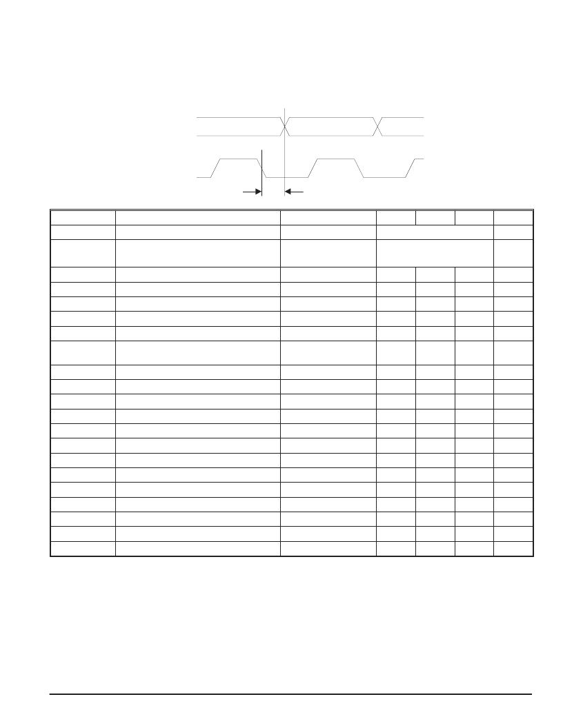
AC Characteristics
T
CASE
= -40 C to +85 C. Appropriate heat sink may be required. Device is DC tested in the temperature range 0 C to 85 C.
Specifications from
–
40 C to 0 C are guaranteed by design and evaluated during the engineering test.
V
CC
= 2.97 V to 3.6 V.
All data given below is reference to STM-16 / OC-48 input data rate unless otherwise stated.
Symbol:
Characteristic
:
Conditions:
MIN.:
TYP.:
MAX.:
UNIT.:
J
TRF
Jitter Transfer
See Figure 8 on
page 10
MHz
J
TOL
Jitter Tolerance
Note 1
See Figure 9 on
page 10
UI
p-p
Jpeak
Jitter Peaking
0.08
dB
Jgen
Jitter Generation
2
23
-1 PRBS , Note 2
8
mUIrms
t
R / tF
Rise/Fall Times SDOP/SDON
20% - 80%
40
90
ps
R
CAPT
Capture Range
-500
500
ppm
t
A
Acquisition Time
2
23
-1 PRBS
50
500
s
L
CID
Consecutive Identical Bits Sustained by
VCO
# of bits with
no transistion
400
1000
bits
L
LOCK_DET
LOCK_DET low to high
SDI off
103
130
ns
LOCK_DET high to low
SDI on
412
514
s
L
LOS_DET
LOS_DET low to high
BER above preset level
26
s
LOS_DET high to low
BER below preset level
131
316
s
t
D
,
DO
Output Phase Delay (see Figure above)
-50
-10
50
ps
D
DUTY
SDO
Output Data Duty Cycle Deviation
45
55
%
C
DUTY
SCO
Output Clock Duty Cycle Deviation
45
55
%
Decision Level Adjustable Range
Maximum swing = 100%
30
50
70
%
Decision Level Deviation
-3
+3
%
D
C
Input Data / PCI Frequency Deviation
Note 3
-200
200
ppm
C
DUTY,
REFCK
Reference Clock Duty Cycle Deviation
Vthr
= -1.3 V
40
60
%
V
OH
CML
CML-output voltage swing
Note 4
400
800
mV
F
VCO
VCO Tuning Range
2.4
2.6
GHz
Note 1:
Note 2:
Note 3:
Note 4:
1 UI
P-P
= 402 ps
5 kHz to 20 MHz, 1 MHz to 20 MHz
Maximum allowable deviation between reference clock and divided VCO clock when locked to data.
With 50
load impedance connected.
Data Sheet Rev.: 21
GD16522
Page 9 of 12
SDO
SCO
t
D
相關(guān)PDF資料 |
PDF描述 |
|---|---|
| GD16592A-48BA | Telecommunication IC |
| GD16K-DIE | ASIC |
| GC25K-DIE | ASIC |
| GC7K-TAB-DIE | ASIC |
| GD25K-DIE | ASIC |
相關(guān)代理商/技術(shù)參數(shù) |
參數(shù)描述 |
|---|---|
| GD16592A-48BA | 制造商:未知廠家 制造商全稱:未知廠家 功能描述:Telecommunication IC |
| GD16K-DIE | 制造商:未知廠家 制造商全稱:未知廠家 功能描述:ASIC |
| GD16K-TAB-DIE | 制造商:未知廠家 制造商全稱:未知廠家 功能描述:ASIC |
| GD1726 | 制造商:Burndy 功能描述:GROUND CONNECTOR |
| GD174C | 制造商:Burndy 功能描述:GROUND CONNECTOR |
發(fā)布緊急采購,3分鐘左右您將得到回復。