- 您現(xiàn)在的位置:買賣IC網(wǎng) > PDF目錄67602 > G751 (Global Mixed-mode Technology Inc.) Digital Temperature Sensor and Thermal Watchdog with Two-Wire Interface PDF資料下載
參數(shù)資料
| 型號: | G751 |
| 廠商: | Global Mixed-mode Technology Inc. |
| 元件分類: | 溫度/濕度傳感器 |
| 英文描述: | Digital Temperature Sensor and Thermal Watchdog with Two-Wire Interface |
| 中文描述: | 數(shù)字溫度傳感器和雙線接口熱看門狗 |
| 文件頁數(shù): | 7/11頁 |
| 文件大小: | 268K |
| 代理商: | G751 |
Ver: 2.4
Nov 26, 2002
TEL: 886-3-5788833
http://www.gmt.com.tw
5
G751
Global Mixed-mode Technology Inc.
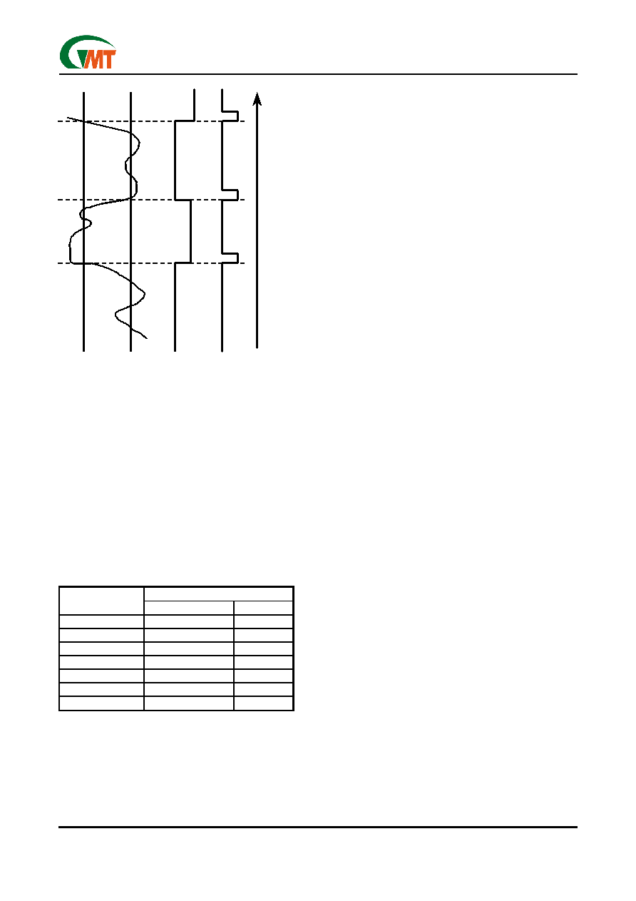
Figure1 O.S. Output Temperature Response Diagram
Temperature Data Format
Temperature data can be read from the Temperature,
TOS Set Point, and THYST Set Point registers; and
written to the TOS Set Point, and THYST Set Point reg-
isters. Temperature data is represented
by a 9-bit, two’s complement word with an LSB
(Least Significant Bit) equal to 0.5°C:
DIGITAL OUTPUT
TEMPERATURE
BINARY
HEX
+125°C
0 1111 1010
0FAh
+25°C
0 0011 0010
032h
+0.5°C
0 0000 0001
001h
0°C
0 0000 0000
000h
-0.5°C
1 1111 1111
1FFh
-25°C
1 1100 1110
1CEh
-55°C
1 1001 0010
192h
Shutdown Mode
Shutdown mode is enabled by setting the shutdown
bit in the Configuration register via the SMBus. Shut-
down mode reduces power supply current to 1 A
typical. In interrupt mode O.S. is reset if previously
set and is undefined in Compatator mode during
shutdown. The SMBus interface remains active. Ac-
tivity on the clock and data lines of the SMBus may
slightly increase shutdown mode quiescent current.
TOS, THYST, and Configuration registers can be read
from and written to in shutdown mode.
Fault Queue
A fault queue of up to 6 faults is provided to prevent
false tripping of O.S. when the G751 is used in noisy
environments. The number of faults set in the queue
must occur consecutively to set the O.S. output.
Comparator/Interrupt Mode
As indicated in the O.S. Output Temperature Re-
sponse Diagram, Figure 1, the events that trigger
O.S. are identical for either Comparator or Interrupt
mode. The most important difference is that in Inter-
rupt mode the O.S. will remain set indefinitely once it
has been set. To reset O.S. while in Interrupt mode,
perform a read from any register in the G751.
O.S. Output
The O.S. output is an open-drain output and does
not have an internal pull-up. A ”high” level will not be
observed on this pin until pull-up current is provided
from some external source, typically a pull-up resis-
tor. Choice of resistor value depends on many sys-
tem factors but, in general, the pull-up resistor
should be as large as possible. This will minimize
any errors due to internal heating of the G751. The
maximum resistance of the pull up, based on G751
specification for High Level Output Current, to pro-
vide a 2V high level, is 30k
.
O.S. Polarity
The O.S. output can be programmed via the con-
figuration register to be either active low (default
mode), or active high. In active low mode the O.S.
output goes low when triggered exactly as shown on
the O.S. Output Temperature Response Diagram,
Figure 1. Active high simply inverts the polarity of the
O.S. output.
T
OS
T
HY
S
T
O.
S.
(Com
pa
ra
tor
M
ode
)
O.
S.
(In
terrup
tM
ode
)
Ti
m
e
T
em
per
at
u
re
res
pon
se
S
ho
w
nfo
rO
.S
.s
et
fo
r
a
cti
ve
lo
w
.
*r
ea
d
a
n
y
re
g
is
te
ror
pl
ac
e
d
in
shut
d
o
w
n
*
T
OS
T
HY
S
T
O.
S.
(Com
pa
ra
tor
M
ode
)
O.
S.
(In
terrup
tM
ode
)
Ti
m
e
T
em
per
at
u
re
res
pon
se
S
ho
w
nfo
rO
.S
.s
et
fo
r
a
cti
ve
lo
w
.
*r
ea
d
a
n
y
re
g
is
te
ror
pl
ac
e
d
in
shut
d
o
w
n
*
相關(guān)PDF資料 |
PDF描述 |
|---|---|
| G767F | Remote/Local Temperature Sensor with SMBus Serial Interface |
| G771 | Two Remote Temperature Sensors with SMBus Serial Interface and System Reset Circuit |
| GB082AHGAAMDA-V01 | SPECIFICATIONS FOR LCD MODULE |
| GB082AHGAAMDB-V01 | SPECIFICATIONS FOR LCD MODULE |
| GB082AHGAAMLA-V01 | SPECIFICATIONS FOR LCD MODULE |
相關(guān)代理商/技術(shù)參數(shù) |
參數(shù)描述 |
|---|---|
| G751_05 | 制造商:GMT 制造商全稱:Global Mixed-mode Technology Inc 功能描述:Digital Temperature Sensor and Thermal Watchdog with Two-Wire Interface |
| G751-1 | 制造商:未知廠家 制造商全稱:未知廠家 功能描述:Digital Temperature Sensor and Thermal Watchdog with Two-Wire Interface |
| G751-1P1 | 制造商:GMT 制造商全稱:Global Mixed-mode Technology Inc 功能描述:Digital Temperature Sensor and Thermal Watchdog with Two-Wire Interface |
| G751-2 | 制造商:未知廠家 制造商全稱:未知廠家 功能描述:Digital Temperature Sensor and Thermal Watchdog with Two-Wire Interface |
| G751-2P1 | 制造商:GMT 制造商全稱:Global Mixed-mode Technology Inc 功能描述:Digital Temperature Sensor and Thermal Watchdog with Two-Wire Interface |
發(fā)布緊急采購,3分鐘左右您將得到回復(fù)。