- 您現(xiàn)在的位置:買賣IC網(wǎng) > PDF目錄370297 > G6Y-1-DC6 PDF資料下載
參數(shù)資料
| 型號: | G6Y-1-DC6 |
| 文件頁數(shù): | 5/7頁 |
| 文件大小: | 211K |
| 代理商: | G6Y-1-DC6 |

G6Y
G6Y
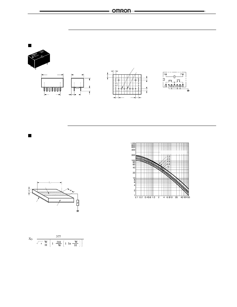
Dimensions
Unit: mm (inch)
G6Y-1
PCB Dimensions
(Bottom View)
Tolerances:
±
0.1 mm.
Six, 1.2-dia. holes
Three, 0.8-dia. holes
(Holes for the coil terminals may also be 1.0.)
Terminal Arrangement/
Internal Connections
(Bottom View)
Note: The shaded and unshaded
parts indicate the product’s
directional marks.
20.7max.
(0.81)
15.24
(0.60)
7.62
(0.30)
1.83
(0.07)
15.24
(0.60)
2.54
(0.10)
2.54
(0.10)
2.63
(0.10)
2.05
(0.08)
2.63
(0.10)
11.7max.
(0.46)
7.62
(0.30)
2.05
(0.08)
9.2max.
(0.36)
3
(0.12)
Precautions
CORRECT USE
Seal integrity during cleaning will last for 1 minute at 70
°
C.
Micro Strip Line Design
It is advantageous to use the Micro Strip Line in high-
frequency transmission circuits because a low-loss trans-
mission can be achieved with this method. By etching the
dielectric base which has copper foil attached to both sides,
the Micro Strip Line will have a concentrated electric field
between the lines and ground, as shown in the following
diagram.
Lines with impedance Z
Ground pattern
Dielectric base
(dielectric constant:
ε
r
)
The characteristic impedance of the lines Z
O
is determined
by the kind of base (dielectric constant), the base’s thickness,
and the width of the lines, as expressed in the following
equation.
=
ε
+
π
+
π
W: Line width
ε
r
: Effective dielectric constant
H: Dielectric base thickness
The copper foil thickness must be less than H.
The following graph shows this relationship.
Micro Strip (w/h)
Dielectric constant (
ε
r
)
M
)
For example, when creating 50-
lines using a glass epoxy
base with a thickness of 1.6 mm, the above graph will yield a
w/h ratio of 1.7 for a dielectric constant of 4.8. Since the base
thickness is 1.6 mm, the width will be h
×
1.7
≈
2.7 mm.
The thickness of the copper foil “t” is ignored in this design
method, but it must be considered because large errors will
occur in extreme cases such as a foil thickness of t
≈
w.
In addition, with the Micro Strip Line design, the lines are too
short for the G6Y’s intended frequency bandwidths, so we
can ignore conductive losses and the line’s attenuation
constant.
The spacing of the Strip Lines and ground pattern should be
comparable to the width of the Strip Lines.
相關PDF資料 |
PDF描述 |
|---|---|
| G6Y-1-DC9 | |
| G709D-10 | G709D-10 10 Gbits/sec ITU G.709 Reed-Solomon Decoder Core - Product Brief |
| G709D2-5 | G709D2-5 2.5 Gbits/sec ITU G.709 Reed-Solomon Decoder Core |
| G709D-40 | G709D-40 40 Gbits/sec ITU G.709 Reed-Solomon Decoder Core |
| G709E2-5 | G709E2-5 2.5 Gbits/sec ITU G.709 Reed-Solomon Encoder Core |
相關代理商/技術參數(shù) |
參數(shù)描述 |
|---|---|
| G6Y1DC9 | 制造商:Omron Electronic Components LLC 功能描述:RELAY RF SPDT 10MA 9V |
| G6Y-1-DC9 | 功能描述:高頻/射頻繼電器 900MHZ SPDT 9VDC FREQ RoHS:否 制造商:Omron Electronics 觸點形式:2 Form C (DPDT-BM) 觸點電流額定值: 線圈電壓:5 VDC 線圈類型:Non-Latching 頻率: 功耗:100 mW 端接類型:Solder Terminal 絕緣:20 dB to 30 dB at 1 GHz 介入損耗:0.2 dB at 1 GHz |
| G6Z | 制造商:OMRON 制造商全稱:Omron Electronics LLC 功能描述:High-frequency Relay |
| G6Z-1F | 制造商:OMRON 制造商全稱:Omron Electronics LLC 功能描述:High-frequency Relay |
| G6Z1-F 12DC | 制造商:Omron Electronic Components LLC 功能描述:RELAY SMD HF SPCO 12VDC |
發(fā)布緊急采購,3分鐘左右您將得到回復。