- 您現(xiàn)在的位置:買賣IC網(wǎng) > PDF目錄223808 > FST8135SM4A (MICROSEMI POWER PRODUCTS GROUP) 40 A, 35 V, SILICON, RECTIFIER DIODE PDF資料下載
參數(shù)資料
| 型號(hào): | FST8135SM4A |
| 廠商: | MICROSEMI POWER PRODUCTS GROUP |
| 元件分類: | 整流器 |
| 英文描述: | 40 A, 35 V, SILICON, RECTIFIER DIODE |
| 封裝: | ROHS COMPLIANT, SM4, 3 PIN |
| 文件頁數(shù): | 1/2頁 |
| 文件大小: | 119K |
| 代理商: | FST8135SM4A |
ROHS Compliant
Electrical Characteristics
Thermal and Mechanical Characteristics
.015
.025
0.38
0.64
.085
.065
2.16
1.65
.260
.240
6.60
6.10
.098
.088
2.49
2.24
.370
.350
9.40
8.89
.110
.120
.100
2.54
2.79
3.04
D
Millimeter
Notes
Maximum
Minimum
Maximum
Minimum
29.97
30.35
1.180
1.195
E
F
G
H
J
K
L
Dim. Inches
26.12
26.42
1.020
1.040
.695
.715
17.65
18.16
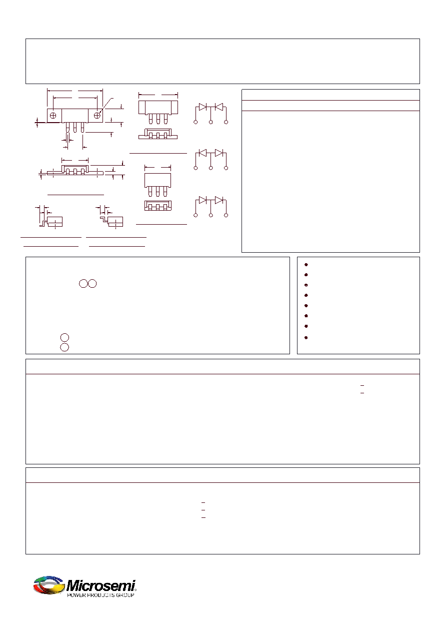
Schottky Power Surface Mount
.110
2.79
FST81SM1-SM6 Series
35V
40V
45V
40V
35V
M
1.490
1.510
37.85
38.35
N
.695
.715
17.65
18.16
.027
.037
0.69
0.94
Microsemi Catalog
Catalog Number
Working Peak
Reverse Voltage
Repetitive Peak
Reverse Voltage
3
2
1
M
3 PINS eq sp at .200
G
C
H
J
N
E
3
2
1
L
3
2
1
F
A1
A2
A3
SM1 & SM2
SM3 & SM4
SM5 & SM6
B
D
A1
A2
A3
B
C
.151
.161
3.84
4.09
FOR SM2, SM4, & SM6
Dia.
TYP. PIN CONFIGURATION
D
B
TYP. PIN CONFIGURATION
FOR SM1, SM3, & SM5
K
T
J
STG
Typical thermal resistance (greased)
Max thermal resistance per pkg.
Max thermal resistance per leg
Operating junction temp range
Storage temp range
ROJC
1.0°C/W
0.5°C/W
0.3 ounce (8.4 grams) typical
Weight
Mounting Base Torque
-55°C to 150°C
-55°C to 175°C
Case to sink
*Pulse test: Pulse width 300sec, Duty cycle 2%
Average forward current per pkg
Average forward current per leg
Maximum surge current per leg
Max repetitive peak reverse current per leg
Max peak forward voltage per leg
Max peak reverse current per leg
Typical junction capacitance per leg
F(AV) 80 Amps
F(AV) 40 Amps
FSM 800 Amps
R(OV)
2 Amps
FM 0.47 volts
FM 0.53 volts
RM 500 mA
J
2100 pF
RM 3.0 mA
I
V
I
C
C = 110°C, Square wave,
0JC = 0.5°C/W
C = 110°C, Square wave,
0JC = 1.0°C/W
8.3 ms, half sine,
J = 150°C
f = 1 KHZ, 25°C, 1sec square wave
FM = 40A:
J = 150°C*
FM = 40A:
J = 25°C*
RRM,
C = 125°C*
RRM,
J = 25°C
R = 5.0V,
C = 25°C
R
V
I
T
.230
.250
5.84
6.35
2 Specify C-Common Cathode, A-Common Anode, D-Doubler
10 inch pounds maximum (SM1, 2)
SM1-2
SM3-4
ounce (
grams) typical
ounce (
grams) typical
Note: 1 Specify (1-6) to identify package desired
FST8135SM _ _
FST8140SM _ _
FST8145SM _ _
1 2
6.7
5.2
0.24
0.18
SM5-6
T
OJC
R
Junction to case
0.3°C/W
OCS
R
Note: Baseplate Common with Pin 2
2-PLCS.
D=Doubler
A=Common Anode
Common Cathode
1
2
1
2
1
2
3
Max peak reverse current per leg
Industry
Part Number
80CNQ035ASL
80CNQ040ASL
80CNQ045ASL
80CNQ035ASM
80CNQ040ASM
80CNQ045ASM
2 X 40 Amperes Avg.
150°C Junction Temperature
Low Forward Voltage
Common Cathode
Center Tap
Guard Ring Protection
Schottky Barrier Rectifier
Reverse Energy Tested
January, 2010 - Rev. 4
www.microsemi.com
相關(guān)PDF資料 |
PDF描述 |
|---|---|
| FT2232HQ-TRAY | |
| FT2232HL-TRAY | |
| FT245BL | |
| FT245BQ | |
| FT245BM | |
相關(guān)代理商/技術(shù)參數(shù) |
參數(shù)描述 |
|---|---|
| FST8135SM5 | 制造商:MICROSEMI 制造商全稱:Microsemi Corporation 功能描述:Schottky Power Surface Mount |
| FST8135SM6 | 制造商:MICROSEMI 制造商全稱:Microsemi Corporation 功能描述:Schottky Power Surface Mount |
| FST8135SMA | 制造商:Microsemi Corporation 功能描述:FST8135SMA - Bulk |
| FST8135SMC | 制造商:MICROSEMI 制造商全稱:Microsemi Corporation 功能描述:Schottky Power Surface Mount |
| FST8135SMD | 制造商:Microsemi Corporation 功能描述:FST8135SMD - Bulk |
發(fā)布緊急采購,3分鐘左右您將得到回復(fù)。