- 您現(xiàn)在的位置:買賣IC網(wǎng) > PDF目錄375932 > FSDM07652RWDTU (FAIRCHILD SEMICONDUCTOR CORP) Green Mode Fairchild Power Switch (FPS) PDF資料下載
參數(shù)資料
| 型號: | FSDM07652RWDTU |
| 廠商: | FAIRCHILD SEMICONDUCTOR CORP |
| 元件分類: | 穩(wěn)壓器 |
| 英文描述: | Green Mode Fairchild Power Switch (FPS) |
| 中文描述: | 15 A SWITCHING REGULATOR, PZFM6 |
| 封裝: | TO-220F, 6 PIN |
| 文件頁數(shù): | 13/20頁 |
| 文件大小: | 262K |
| 代理商: | FSDM07652RWDTU |

FSDM0565R
13
output voltage may exceed the rated voltage before the over
load protection is activated, resulting in the breakdown of the
devices in the secondary side. In order to prevent this
situation, an over voltage protection (OVP) circuit is
employed. In general, Vcc is proportional to the output
voltage and the FPS
TM
uses Vcc instead of directly
monitoring the output voltage. If V
CC
exceeds 19V, an OVP
circuit is activated resulting in the termination of the
switching operation. In order to avoid undesired activation of
OVP during normal operation, Vcc should be designed to be
below 19V.
3.4 Thermal Shutdown (TSD) :
The Sense FET and the
control IC are built in one package. This makes it easy for
the control IC to detect the heat generation from the Sense
FET. When the temperature exceeds approximately 150
°
C,
the thermal shutdown is activated.
4. Soft Start
: The FPS
TM
has an internal soft start circuit
that increases PWM comparator inverting input voltage
together with the Sense FET current slowly after it starts up.
The typical soft start time is 10msec, The pulse width to the
power switching device is progressively increased to
establish the correct working conditions for transformers,
inductors, and capacitors. The voltage on the output
capacitors is progressively increased with the intention of
smoothly establishing the required output voltage. It also
helps to prevent transformer saturation and reduce the stress
on the secondary diode during startup.
5. Burst operation :
In order to minimize power dissipation
in standby mode, the FPS
TM
enters burst mode operation.
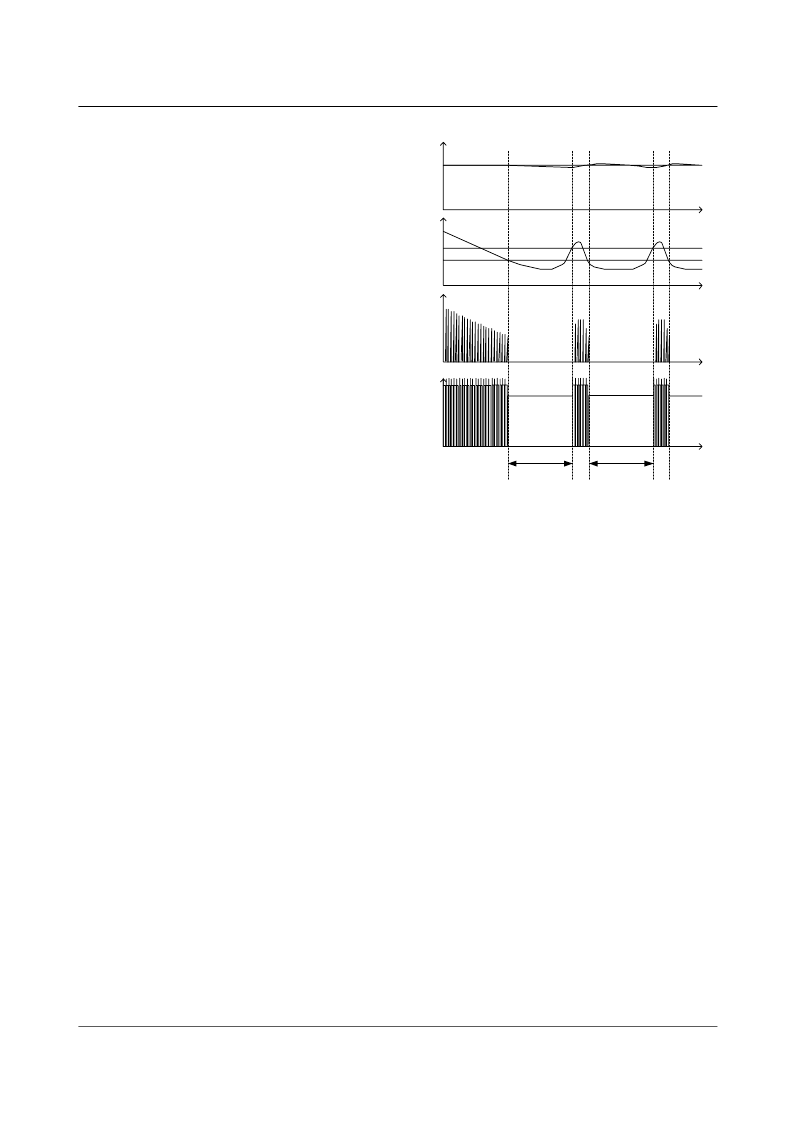
As the load decreases, the feedback voltage decreases. As
shown in figure 9, the device automatically enters burst
mode
when
the
feedback
V
BURL
(500mV). At this point switching stops and the
output voltages start to drop at a rate dependent on standby
current load. This causes the feedback voltage to rise. Once
it passes V
BURH
(700mV) switching resumes. The feedback
voltage then falls and the process repeats. Burst mode
operation alternately enables and disables switching of the
power Sense FET thereby reducing switching loss in
Standby mode.
voltage
drops
below
Figure 9. Waveforms of burst operation
V
FB
V ds
0.5V
0.7V
Ids
Vo
Vo
set
time
Switching
disabled
T1
T2 T3
Switching
disabled
T4
相關(guān)PDF資料 |
PDF描述 |
|---|---|
| FSDM101 | Green Mode Fairchild Power Switch (FPSTM) |
| FSDM1265RBWDTU | Green Mode Fairchild Power Switch (FPS) |
| FSDM1265RB | Green Mode Fairchild Power Switch (FPS) |
| FSDM311 | Green Mode Fairchild Power Switch (FPS) |
| FSDM311L | Green Mode Fairchild Power Switch (FPS) |
相關(guān)代理商/技術(shù)參數(shù) |
參數(shù)描述 |
|---|---|
| FSDM07652RYDTU | 制造商:Fairchild Semiconductor Corporation 功能描述: |
| FSDM0765RB | 制造商:FAIRCHILD 制造商全稱:Fairchild Semiconductor 功能描述:Green-Mode Fairchild Power Switch (FPS⑩) for Quasi-Resonant Operation - Low EMI and High Efficiency |
| FSDM08D9002 | 制造商:Baumer Electric Ag 功能描述: |
| FSDM08D9002/S35 | 制造商:Baumer Electric Ag 功能描述: |
| FSDM-10 | 制造商:RHOMBUS-IND 制造商全稱:Rhombus Industries Inc. 功能描述:FSDM Series FAST / TTL Buffered Single Output Delay Lines |
發(fā)布緊急采購,3分鐘左右您將得到回復(fù)。