- 您現(xiàn)在的位置:買(mǎi)賣(mài)IC網(wǎng) > PDF目錄44810 > FS2540-7RD4TB2 (POWER-ONE INC) 2-OUTPUT 100 W DC-DC REG PWR SUPPLY MODULE PDF資料下載
參數(shù)資料
| 型號(hào): | FS2540-7RD4TB2 |
| 廠商: | POWER-ONE INC |
| 元件分類: | 電源模塊 |
| 英文描述: | 2-OUTPUT 100 W DC-DC REG PWR SUPPLY MODULE |
| 封裝: | METAL, CASE S02, MODULE |
| 文件頁(yè)數(shù): | 16/33頁(yè) |
| 文件大?。?/td> | 438K |
| 代理商: | FS2540-7RD4TB2 |
第1頁(yè)第2頁(yè)第3頁(yè)第4頁(yè)第5頁(yè)第6頁(yè)第7頁(yè)第8頁(yè)第9頁(yè)第10頁(yè)第11頁(yè)第12頁(yè)第13頁(yè)第14頁(yè)第15頁(yè)當(dāng)前第16頁(yè)第17頁(yè)第18頁(yè)第19頁(yè)第20頁(yè)第21頁(yè)第22頁(yè)第23頁(yè)第24頁(yè)第25頁(yè)第26頁(yè)第27頁(yè)第28頁(yè)第29頁(yè)第30頁(yè)第31頁(yè)第32頁(yè)第33頁(yè)
Description of Options
Table 17: Survey of options
Option
Function of Option
Characteristics
-9
Extended operational ambient temperature range
TA = –40 to 71 °C
E
Electronic inrush current limitation circuitry
Active inrush current limitation for CK, DK, EK
P
Potentiometer for fine adjustment of output voltage
Adjustment range +10/–60% of
Vo nom (R input not connected)
D
1
Input and/or output undervoltage monitoring circuitry
Safe data signal output (versions D0 - DD)
V
1, 2
Input (and output) undervoltage monitoring circuitry
ACFAIL signal according to VME specs (versions V0, V2, V3)
T
Current sharing
Interconnect T-pins if paralleling outputs (5 converters max.)
B1/B2
Cooling plate
Replaces standard heat sink, allowing direct chassis-mounting
1 Option D excludes Option V and vice versa.
2 Only available for V
o = 5.1 V.
Table 18: Inrush current characteristics with option E
(DC-DC converters)
Characteristics
CS
DS
ES
FS
Unit
Vi nom, Io nom
Input voltage
60
110
220
48
V
Iinr p
Peak inrush
6.8
7.4
14.6
4.5
A
current
tinr
Inrush current
18
14
16
22
ms
duration
Vi max, Io nom
Input voltage
140
220
380
100
V
Iinr p
Peak inrush
9.3
14.5
25.3
7.5
A
current
tinr
Inrush current
20
14
12
23
ms
duration
S Series Data Sheet
100 Watt AC-DC and DC-DC Converters
APR 26, 2006 revised to SEP 25, 2006
Page 23 of 33
www.power-one.com
Option -9: Extended Temperature Range
Option -9 extends the operational ambient temperature range
from –25 to 71 °C to –40 to 71 °C. The power supplies provide
full nominal output power with convection cooling. Option -9
excludes inrush current limitation by NTC.
Option E: Inrush Current Limiter
CS/DS/ES/FS/LS types may be supplemented by an electronic
circuit (option E, replacing the standard built-in NTC) to achieve
an enhanced inrush current limiting function.
Option E is
mandatory for -9 models.
CS models fitted with option E and option D6 (input voltage
monitoring) meet the standard ETS 300132-2 for 48 VDC supply
voltage. Option D6 (externally adjustable via potentiometer from
36.0 to 40.5 V) is necessary to disable the converter at low input
voltages, avoiding an excessive input current. Option D6
threshold level should be adjusted to 44.0 - 50.0 V for 60 V
nominal supply systems (refer to the description of option D). The
D output can be connected directly to the inhibit input.
Note: Subsequent switch-on cycles at startup are limited to max.
10 cycles during the first 20 seconds (cold model) and then to
max. 1 cycle every 8 seconds.
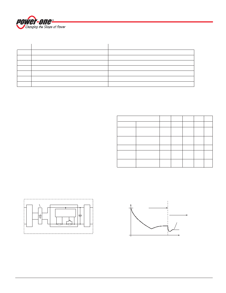
Input
Filter
Control
Converter
FET
Ci
RI
RS
10017_111105
Rectifier (only AC-DC models)
Fig. 25
Option E block diagram
Current limiting resistance = RS + RI = 15 Ω (all models)
I [A]
Vi/RV
<30
t [ms]
Capacitor
Ci
fully charged
Normal operation
(current limiting
circuit is fully
conducting)
0
Ii = Pi/Vi
11039_052605
Fig. 26
Inrush current with option E (DC-DC converters)
相關(guān)PDF資料 |
PDF描述 |
|---|---|
| FS2660-7ERD4B2 | 2-OUTPUT 100 W DC-DC REG PWR SUPPLY MODULE |
| FS2660-7PD6B2 | 2-OUTPUT 100 W DC-DC REG PWR SUPPLY MODULE |
| FS2660-9PD9B2 | 2-OUTPUT 100 W DC-DC REG PWR SUPPLY MODULE |
| FS1001-7EPD9 | 1-OUTPUT DC-DC REG PWR SUPPLY MODULE |
| FS1001-7PD7T | 1-OUTPUT DC-DC REG PWR SUPPLY MODULE |
相關(guān)代理商/技術(shù)參數(shù) |
參數(shù)描述 |
|---|---|
| FS2540-9ER | 制造商:Power-One 功能描述:DCDC - Bulk |
| FS25R06KF | 制造商:未知廠家 制造商全稱:未知廠家 功能描述:TRANSISTOR | IGBT POWER MODULE | 3-PH BRIDGE | 600V V(BR)CES | 25A I(C) |
| FS25R06KF2 | 制造商:未知廠家 制造商全稱:未知廠家 功能描述:TRANSISTOR | IGBT POWER MODULE | 3-PH BRIDGE | 600V V(BR)CES | 25A I(C) |
| FS25R10KF2 | 制造商:未知廠家 制造商全稱:未知廠家 功能描述:TRANSISTOR | IGBT POWER MODULE | 3-PH BRIDGE | 1KV V(BR)CES | 25A I(C) |
| FS25R12KE3G | 功能描述:IGBT 模塊 N-CH 1.2KV 40A RoHS:否 制造商:Infineon Technologies 產(chǎn)品:IGBT Silicon Modules 配置:Dual 集電極—發(fā)射極最大電壓 VCEO:600 V 集電極—射極飽和電壓:1.95 V 在25 C的連續(xù)集電極電流:230 A 柵極—射極漏泄電流:400 nA 功率耗散:445 W 最大工作溫度:+ 125 C 封裝 / 箱體:34MM 封裝: |
發(fā)布緊急采購(gòu),3分鐘左右您將得到回復(fù)。