- 您現(xiàn)在的位置:買賣IC網(wǎng) > PDF目錄299036 > EUS34-096-PHCRC (CD TECHNOLOGIES INC) 1-OUTPUT DC-DC REG PWR SUPPLY MODULE PDF資料下載
參數(shù)資料
| 型號(hào): | EUS34-096-PHCRC |
| 廠商: | CD TECHNOLOGIES INC |
| 元件分類: | 電源模塊 |
| 英文描述: | 1-OUTPUT DC-DC REG PWR SUPPLY MODULE |
| 封裝: | ROHS COMPLIANT, PACKAGE-5 |
| 文件頁數(shù): | 2/3頁 |
| 文件大?。?/td> | 517K |
| 代理商: | EUS34-096-PHCRC |
CDC_EUS34-096.A04 Page 2 of 3
EUS34-096
Isolated Bus Converter
P O W E R E L E C T R O N I C S D I V I S I O N
D C / D C C O N V E R T E R S
www.cd4power.com
Technical enquiries email: toronto@cdtechno.com, tel: (866) 740 232
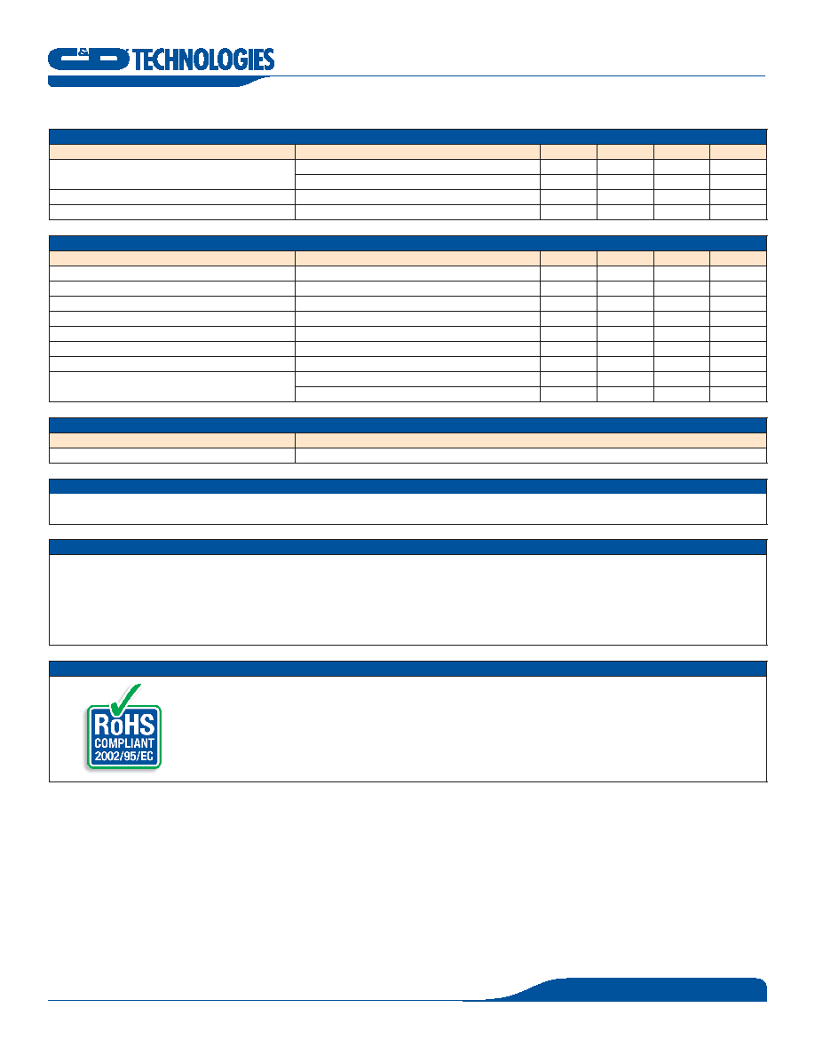
PROTECTION CHARACTERISTICS
Parameter
Conditions
Min.
Typ.
Max.
Units
Output over-current shutdown2
Auto-restart
38
40
42
A
Re-start rate
TBD
ms
Over temperature shutdown3
Auto-restart
35
40
C
Over temperature restart hysteresis
0
C
GENERAL CHARACTERISTICS
Parameter
Conditions
Min.
Typ.
Max.
Units
Isolation voltage
Input to output
2250
VDC
Isolation resistance
Input to output
0
MΩ
Storage temperature range
Non-condensing
-40
25
C
Operating temperature range
-40
85
C
Operating humidity
Non-condensing
0
90
%
Thermal measurement location temperature3
See mechanical drawing for location
30
C
Material flammability
UL 94V-0
MTBF
Calculated per Mil Spec 27 E, or Bellcore at Ta=30C
2
x06 Hrs
Demonstrated
.3
x06 Hrs
STANDARDS COMPLIANCE
Standards
Conditions4
UL/CSA 60950
Basic insulation
MANUFACTURING TESTING
nBurn-in test
nParametric test
SAFETY CONSIDERATIONS
This series of converters are certified to the standards and extent listed in the ‘Standards Compliance’ section in the table above. If this product is built into
information technology equipment, the installation must comply with the above standard. Even though the product is safety certified to operate without an input
fuse, it is recommended that an input fuse of 2A (max.) is used.
The output of the converter (Vo+/Vo-) is considered to remain within SELV limits when the input to the converter meets SELV or TNV-2 requirements. The
converters and materials meet UL 94V-0 flammability ratings.
RoHS COMPLIANCE
The EUS34-096 converter is in compliance with the European Union Directive 2002/95/EC (RoHS) with respect to the
following substances: lead (Pb), cadmium (Cd), mercury (Hg), hexavalent chromium, polybrominated biphenyls (PBB) and
polybrominated diphenyl ethers (PBDE).
For further information, please visit www.cd4power.com/rohs
VIN = 48Vdc, Ta = 25C, Airflow = 200 LFM for all data unless otherwise noted.
2 Input transient: if input voltage increases by 5V in s, output over-current shut-down shall not be triggered (tested with Max. load and Max. output capacitance).
3 Thermal shutdown is monitored at the Thermal Measurement Location (TML). See ‘Mechanical Information’ on page 3 for TML location.
4 See ‘Safety Considerations’ shown on page 4.
Derating curves are conducted in a controlled environment. End application testing is required to ensure the Thermal Measurement Location temperature is below the maximum specified.
Recommended airflow direction is from pin to pin 3, or 3 to (transversal to the unit).
相關(guān)PDF資料 |
PDF描述 |
|---|---|
| EW930092-00 | FEMALE-FEMALE, RF STRAIGHT ADAPTER, JACK |
| EW930092-20 | MALE-FEMALE, RF STRAIGHT ADAPTER, PLUG-JACK |
| EW940021-00 | MALE-FEMALE, RF STRAIGHT ADAPTER, PLUG-JACK |
| EW940021-10 | PANEL MOUNT, FEMALE-FEMALE, RF STRAIGHT ADAPTER |
| EW940021-20 | FEMALE-FEMALE, RF STRAIGHT ADAPTER, JACK |
相關(guān)代理商/技術(shù)參數(shù) |
參數(shù)描述 |
|---|---|
| EUS34-096-PHCRVC | 制造商:MURATA-PS 制造商全稱:Murata Power Solutions Inc. 功能描述:Isolated Bus Converter |
| EUS-44-01455 | 制造商:EAO International 功能描述:PB/IL/MO/LED/1/1/RE/G |
| EUS-44-02255 | 制造商:EAO International 功能描述:PB/IL/MA/LED/1/1/FR/G |
| EUS-44-06552 | 制造商:EAO International 功能描述:EST/TWS.R/MA/1/1/FR |
| EUS-44-06562 | 制造商:EAO International 功能描述:EST/TWS.R/MA/2/2/FR |
發(fā)布緊急采購,3分鐘左右您將得到回復(fù)。