- 您現(xiàn)在的位置:買賣IC網(wǎng) > PDF目錄382951 > ES51988 (Electronic Theatre Controls, Inc.) 3 3/4 AUTO REL/MAX/MIN PDF資料下載
參數(shù)資料
| 型號: | ES51988 |
| 廠商: | Electronic Theatre Controls, Inc. |
| 英文描述: | 3 3/4 AUTO REL/MAX/MIN |
| 中文描述: | 3 3 / 4自動REL /最大值/最小值 |
| 文件頁數(shù): | 3/22頁 |
| 文件大?。?/td> | 254K |
| 代理商: | ES51988 |

3 91年11月28日
3 3/4 AUTO REL/MAX/MIN
ES51988
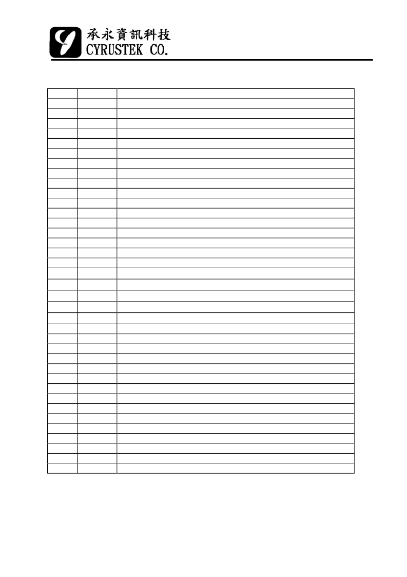
Pin Description
Pin No. Symbol
1
2
3
4
5
6
7
8
9
10
11
12
13
14
15
16
17
18
19
20
21
22
23
24
25
26
27
28
29
30
31
32
33
34
35
36
37
Description
Positive supply voltage,output of on-chip DC-DC converter.
Positive supply voltage,output of on-chip DC-DC converter.
High speed positive connection for reference capacitor.
High speed negative connection for reference capacitor.
High speed integrator output. Connected to integration capacitor.
Integration resistor connection for high speed buffer output.
High speed auto-zero capacitor connection
High resolution positive connection for reference capacitor.
High resolution negative connection for reference capacitor.
High resolution integrator output. Connected to integration capacitor.
High resolution auto-zero capacitor connection.
Integration resistor connection for high resolution buffer output.
High level current measurement input.
Low level current measurement input
Input high voltage for resistance measurement.
Output connection for resistance measurement.
Sense low voltage for resistance measurement.
Reference resistor connection for 399.9
Ω
range.
Voltage measurement
÷
10000 attenuator (3999V).
Voltage measurement
÷
1000 attenuator (399.9V).
Voltage measurement
÷
100 attenuator (39.99V).
Voltage measurement
÷
10 attenuator (3.999V).
Test pin 5.
Negative output of AC to DC converter.
Positive output of AC to DC converter.
Negative input of internal AC to DC OP AMP.
Output of internal AC to DC OP AMP.
V+
V+
CH+
CH-
CIH
BUFH
CAZH
CL+
CL-
CIL
CAZL
BUFL
IVSH
IVSL
OVX
OVH
OVSG
OR1
VR5
VR4
VR3
VR2
TEST5
ACVL
ACVH
ADI
ADO
NC
NC
NC
SGND
VR1
NC
VR
VRH
ACVR
NC
Signal ground.
Unknown voltage input .
Reference input voltage connection. Typically -100 mV.
Output of band-gap voltage reference. Typically -1.2 V.
Optional pin. When connected to -3V,ACV without 400mV range.
相關(guān)PDF資料 |
PDF描述 |
|---|---|
| ES52110 | 8-bit D/A Converter |
| ES62UL256 | 32Kx8 Bit Ultra-Low Power Asynchronous Static RAM |
| ES62UL256-25SC | REED RELAY |
| ES62UL256-25TC | REED RELAY, SPST, 5 VDC COIL VOLTAGE, CONTACT CURRENT RATING AC 1 A, CONTACT CURRENT RATING DC 1 A, PCB MOUNTING, REED RELAY |
| ES62UL256-45SC | REED RELAY |
相關(guān)代理商/技術(shù)參數(shù) |
參數(shù)描述 |
|---|---|
| ES51989 | 制造商:CYRUSTEK 制造商全稱:CYRUSTEK 功能描述:3 3/4 PEAK AUTO DMM |
| ES51990 | 制造商:CYRUSTEK 制造商全稱:CYRUSTEK 功能描述:DMM Analog front end |
| ES51991 | 制造商:CYRUSTEK 制造商全稱:CYRUSTEK 功能描述:11,000 Counts ADC |
| ES51992 | 制造商:CYRUSTEK 制造商全稱:CYRUSTEK 功能描述:11,000 Counts ADC |
| ES51993 | 制造商:CYRUSTEK 制造商全稱:CYRUSTEK 功能描述:11,000 Counts ADC |
發(fā)布緊急采購,3分鐘左右您將得到回復(fù)。