- 您現(xiàn)在的位置:買賣IC網(wǎng) > PDF目錄362765 > ER2A-T3 (Won-Top Electronics Co., Ltd.) 2.0A SURFACE MOUNT SUPER FAST RECTIFIER PDF資料下載
參數(shù)資料
| 型號(hào): | ER2A-T3 |
| 廠商: | Won-Top Electronics Co., Ltd. |
| 英文描述: | 2.0A SURFACE MOUNT SUPER FAST RECTIFIER |
| 中文描述: | 2.0安培表面貼裝超快速整流 |
| 文件頁(yè)數(shù): | 1/3頁(yè) |
| 文件大小: | 51K |
| 代理商: | ER2A-T3 |
ER2A – ER2J
1 of
3
200
2
Won-Top Electronics
ER2A – ER2J
2.0A SURFACE MOUNT SUPER FAST RECTIFIER
Features
!
Glass Passivated Die Construction
!
Ideally Suited for Automatic Assembly B
!
Low Forward Voltage Drop, High Efficiency
!
Surge Overload Rating to 50A Peak D
!
Low Power Loss A
!
Super-Fast Recovery Time F
!
Plastic Case Material has UL Flammability
Classification Rating 94V-O C H G
E
Mechanical Data
!
Case: Low Profile Molded Plastic
!
Terminals: Solder Plated, Solderable
per MIL-STD-750, Method 2026
!
Polarity: Cathode Band or Cathode Notch
!
Marking: Type Number
!
Weight: 0.093 grams (approx.)
Maximum Ratings and Electrical Characteristics
@T
A
=25°C unless otherwise specified
Characteristic
Symbol
ER2A
ER2B
ER2C
ER2D
ER2E
ER2G
ER2J
Unit
Peak Repetitive Reverse Voltage
Working Peak Reverse Voltage
DC Blocking Voltage
V
RRM
V
RWM
V
R
50
100
150
200
300
400
600
V
RMS Reverse Voltage
V
R(RMS)
35
70
105
140
210
280
420
V
Average Rectified Output Current @T
L
= 110°C
I
O
2.0
A
Non-Repetitive Peak Forward Surge Current
8.3ms Single half sine-wave superimposed on
rated load (JEDEC Method)
I
FSM
50
A
Forward Voltage @I
F
= 2.0A
V
FM
0.95
1.25
1.7
V
Peak Reverse Current @T
A
= 25°C
At Rated DC Blocking Voltage @T
A
= 100°C
I
RM
5.0
500
μA
Reverse Recovery Time (Note 1)
t
rr
35
nS
Typical Junction Capacitance (Note 2)
C
j
25
pF
Typical Thermal Resistance (Note 3)
R
JL
20
K/W
Operating and Storage Temperature Range
T
j,
T
STG
-65 to +150
°C
Note: 1. Measured with I
F
= 0.5A, I
R
= 1.0A, I
rr
= 0.25A,
2. Measured at 1.0 MHz and applied reverse voltage of 4.0 V DC.
3. Mounted on P.C. Board with 8.0mm
2
land area.
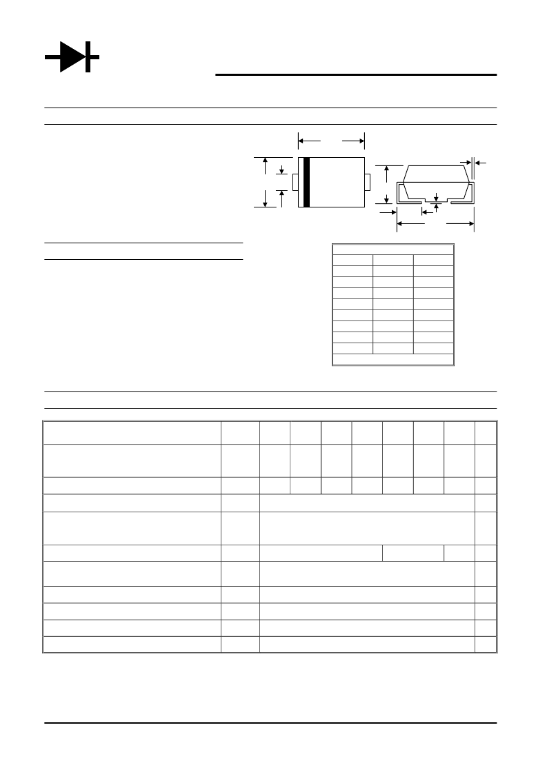
WTE
POWER SEMICONDUCTORS
SMB/DO-214AA
Min
3.30
4.06
1.91
0.152
5.08
2.13
0.051
0.76
All Dimensions in mm
Dim
A
B
C
D
E
F
G
H
Max
3.94
4.70
2.11
0.305
5.59
2.44
0.203
1.27
相關(guān)PDF資料 |
PDF描述 |
|---|---|
| ER2G-T3 | 2.0A SURFACE MOUNT SUPER FAST RECTIFIER |
| ER2E-T1 | 2.0A SURFACE MOUNT SUPER FAST RECTIFIER |
| ER2E-T3 | 2.0A SURFACE MOUNT SUPER FAST RECTIFIER |
| ER2D-T1 | 2.0A SURFACE MOUNT SUPER FAST RECTIFIER |
| ER2D-T3 | 2.0A SURFACE MOUNT SUPER FAST RECTIFIER |
相關(guān)代理商/技術(shù)參數(shù) |
參數(shù)描述 |
|---|---|
| ER2A-TP | 制造商:Micro Commercial Components (MCC) 功能描述:Diode Switching 50V 2A 2-Pin HSMB T/R |
| ER2B | 制造商:CHONGQING 制造商全稱:CHONGQING 功能描述:SUPER FAST RECOVERY RECTIFIER |
| ER2B_R1_00001 | 制造商:PanJit Touch Screens 功能描述: |
| ER2B_R2_00001 | 制造商:PanJit Touch Screens 功能描述: |
| ER2B1 | 制造商:MICROSEMI 制造商全稱:Microsemi Corporation 功能描述:3 AMP ENCAPSULATED ASSEMBLIES |
發(fā)布緊急采購(gòu),3分鐘左右您將得到回復(fù)。