- 您現(xiàn)在的位置:買賣IC網(wǎng) > PDF目錄362657 > ELANSC410-33AI (ADVANCED MICRO DEVICES INC) 5566-12BGS /N/MINI FIT CONN HOUS ASSY PDF資料下載
參數(shù)資料
| 型號(hào): | ELANSC410-33AI |
| 廠商: | ADVANCED MICRO DEVICES INC |
| 元件分類: | 微控制器/微處理器 |
| 英文描述: | 5566-12BGS /N/MINI FIT CONN HOUS ASSY |
| 中文描述: | 32-BIT, FLASH, 33 MHz, MICROCONTROLLER, PBGA292 |
| 封裝: | PLASTIC, BGA-292 |
| 文件頁數(shù): | 68/132頁 |
| 文件大小: | 2400K |
| 代理商: | ELANSC410-33AI |
第1頁第2頁第3頁第4頁第5頁第6頁第7頁第8頁第9頁第10頁第11頁第12頁第13頁第14頁第15頁第16頁第17頁第18頁第19頁第20頁第21頁第22頁第23頁第24頁第25頁第26頁第27頁第28頁第29頁第30頁第31頁第32頁第33頁第34頁第35頁第36頁第37頁第38頁第39頁第40頁第41頁第42頁第43頁第44頁第45頁第46頁第47頁第48頁第49頁第50頁第51頁第52頁第53頁第54頁第55頁第56頁第57頁第58頁第59頁第60頁第61頁第62頁第63頁第64頁第65頁第66頁第67頁當(dāng)前第68頁第69頁第70頁第71頁第72頁第73頁第74頁第75頁第76頁第77頁第78頁第79頁第80頁第81頁第82頁第83頁第84頁第85頁第86頁第87頁第88頁第89頁第90頁第91頁第92頁第93頁第94頁第95頁第96頁第97頁第98頁第99頁第100頁第101頁第102頁第103頁第104頁第105頁第106頁第107頁第108頁第109頁第110頁第111頁第112頁第113頁第114頁第115頁第116頁第117頁第118頁第119頁第120頁第121頁第122頁第123頁第124頁第125頁第126頁第127頁第128頁第129頁第130頁第131頁第132頁
68
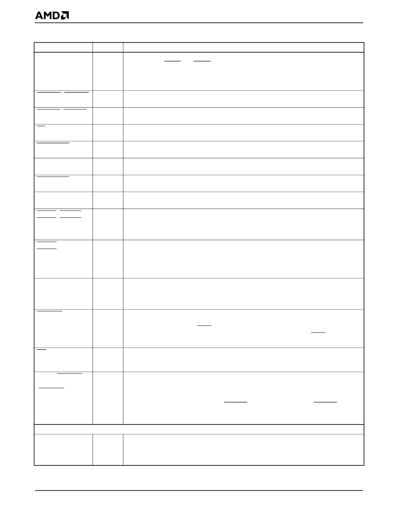
élanSC400 and élanSC410 Microcontrollers Data Sheet
ICDIR
O
Card Data Direction
controls the direction of the card data buffers or voltage translators. It
works with the MCEL and MCEH card enable signals to control data buffers on the card
interface. When this signal is High, the data flow is from the chip to the card socket, indicating
a data write cycle. When this signal is Low, the data flow is from the card socket into the chip,
indicating a read cycle. This signal is not supported on the élanSC410 microcontroller.
Card Enables, High Byte
enables a PC Card’s high data bus byte transceivers for the
respective card interfaces. These signals are not supported on the élanSC410 microcontroller.
Card Enables, Low Byte
enables a PC Card’s low data bus byte transceivers for the
respective card interfaces. These signals are not supported on the élanSC410 microcontroller.
PC Card Output Enable:
This is the PC Card memory read signal. This signal is not
supported on the élanSC410 microcontroller.
PC Card Socket A V
CC
Enable
can be used to control the V
CC
to Socket A. This signal is
not supported on the élanSC410 microcontroller.
PC Card Socket A VPP Selects
can be used to control the V
PP
to Socket A. These signals
are not supported on the élanSC410 microcontroller.
PC Card Socket B V
CC
Enable
can be used to control the V
CC
to Socket B. This signal is
not supported on the élanSC410 microcontroller.
PC Card Socket B VPP Selects
can be used to control the V
PP
to Socket B. These signals
are not supported on the élanSC410 microcontroller.
Card Ready
indicates that the respective card is ready to accept a new data transfer
command. When the card interface is configured as an I/O interface, this signal is used as
the card Interrupt Request input into the chip. These signals are not supported on the
élanSC410 microcontroller.
Attribute Memory Select
signals
are driven inactive (High) for accesses to a PC Card’s
common memory, and asserted (Low) for accesses to a PC Card’s attribute memory and
I/O space for their respective card interfaces. When PC Card DMA is enabled, the DMA
acknowledge to the PC Card appears on this signal. These signals are not supported on the
élanSC410 microcontroller.
Card Reset
signals are the reset for their respective cards. When active, this signal clears
the Interrupt and General Control Register (PC Card index 03h and 43h), thus placing a card
in an unconfigured (Memory-Only mode) state. It also indicates the beginning of any additional
card initialization. These signals are not supported on the élanSC410 microcontroller.
Extend Bus Cycle
delays the completion of the memory access or I/O access that is
currently in progress. When this signal is asserted (Low), wait states are inserted into the
cycle in progress. Only one WAIT input is provided on the chip. External logic is required for
a two-socket implementation to logically AND (digitally OR) each card’s WAIT signal
together. This signal is not supported on the élanSC410 microcontroller.
PC Card Write Enable
is the PC Card memory write signal. Data is transferred from the chip
to the PC Card. When PC Card DMA is enabled, the DMA Terminal Count to the PC Card
appears on this signal. This signal is not supported on the élanSC410 microcontroller.
Write Protect
indicates the status of the respective card’s Write Protect switch. When the
respective card is configured for an I/O interface, this signal is used by the card to indicate
back to the chip that the currently accessed port is 16 bits wide. When PC Card DMA is
enabled, the DMA request from the PC Card can be programmed to appear on this signal.
See also the description for BVD2_A (SPKR_A) (DRQ_A) and BVD2_B (SPKR_B)
(DRQ_B); the DMA request can also be programmed to appear on these pins. These signals
are not supported on the élanSC410 microcontroller.
LCD Graphics Controller (élanSC400 Microcontroller Only)
FRM
O
LCD Panel Line Frame Start
is asserted by the chip at the start of every frame to indicate
to the LCD panel that the next data clocked out is intended for the start of the first scan line
on the panel. Some panels refer to this signal as FLM or S (scan start-up). This signal is not
supported on the élanSC410 microcontroller.
MCEH_A, MCEH_B
O
MCEL_A, MCEL_B
O
OE
O
PCMA_VCC
O
PCMA_VPP2–
PCMA_VPP1
PCMB_VCC
O
O
PCMB_VPP2–
PCMB_VPP1
RDY_A (IREQ_A),
RDY_B (IREQ_B)
O
I
REG_A (DACK_A),
REG_B (DACK_B)
O
RST_A, RST_B
O
WAIT_AB
I
WE (TC)
O
WP_A (IOIS16_A)
(DRQ_A), WP_B
(IOIS16_B)
(DRQ_B)
I
Table 19.
Signal Description Table (Continued)
Signal
Type
Description
相關(guān)PDF資料 |
PDF描述 |
|---|---|
| ELANSC410-66AC | Single-Chip, Low-Power, PC/AT-Compatible Microcontrollers |
| ELANSC410-66AI | Single-Chip, Low-Power, PC/AT-Compatible Microcontrollers |
| ELANSC400ANDELANSC410 | Single Synchronous Buck Pulse-Width Modulation (PWM) Controller; Temperature Range: 0°C to 70°C; Package: 14-SOIC T&R |
| ELANSC400 | Single-Chip, Low-Power, PC/AT-Compatible Microcontrollers |
| ELANSC400-100AC | Single-Chip, Low-Power, PC/AT-Compatible Microcontrollers |
相關(guān)代理商/技術(shù)參數(shù) |
參數(shù)描述 |
|---|---|
| ELANSC410-66AC | 制造商:Advanced Micro Devices 功能描述:MCU 32-bit Elan RISC ROMLess 3.3V 292-Pin BGA 制造商:Advanced Micro Devices 功能描述:MCU 16-Bit/32-Bit Elan CISC 3.3V 292-Pin BGA 制造商:Advanced Micro Devices 功能描述:Microprocessor, 32 Bit, 292 Pin, Plastic, BGA |
| ELANSC410-66ACAD | 制造商:Advanced Micro Devices 功能描述: |
| ELANSC410-66AI | 制造商:Advanced Micro Devices 功能描述:MCU 16-Bit/32-Bit Elan CISC ROMLess 3.3V 292-Pin BGA |
| ELANSC520 | 制造商:AMD 制造商全稱:Advanced Micro Devices 功能描述:Microcontroller |
| ELANSC520100AC | 制造商:Advanced Micro Devices 功能描述: |
發(fā)布緊急采購,3分鐘左右您將得到回復(fù)。