- 您現(xiàn)在的位置:買賣IC網(wǎng) > PDF目錄362657 > ELANSC410-100AC (ADVANCED MICRO DEVICES INC) Single-Chip, Low-Power, PC/AT-Compatible Microcontrollers PDF資料下載
參數(shù)資料
| 型號(hào): | ELANSC410-100AC |
| 廠商: | ADVANCED MICRO DEVICES INC |
| 元件分類: | 微控制器/微處理器 |
| 英文描述: | Single-Chip, Low-Power, PC/AT-Compatible Microcontrollers |
| 中文描述: | 32-BIT, FLASH, 100 MHz, MICROCONTROLLER, PBGA292 |
| 封裝: | PLASTIC, BGA-292 |
| 文件頁(yè)數(shù): | 63/132頁(yè) |
| 文件大?。?/td> | 2400K |
| 代理商: | ELANSC410-100AC |
第1頁(yè)第2頁(yè)第3頁(yè)第4頁(yè)第5頁(yè)第6頁(yè)第7頁(yè)第8頁(yè)第9頁(yè)第10頁(yè)第11頁(yè)第12頁(yè)第13頁(yè)第14頁(yè)第15頁(yè)第16頁(yè)第17頁(yè)第18頁(yè)第19頁(yè)第20頁(yè)第21頁(yè)第22頁(yè)第23頁(yè)第24頁(yè)第25頁(yè)第26頁(yè)第27頁(yè)第28頁(yè)第29頁(yè)第30頁(yè)第31頁(yè)第32頁(yè)第33頁(yè)第34頁(yè)第35頁(yè)第36頁(yè)第37頁(yè)第38頁(yè)第39頁(yè)第40頁(yè)第41頁(yè)第42頁(yè)第43頁(yè)第44頁(yè)第45頁(yè)第46頁(yè)第47頁(yè)第48頁(yè)第49頁(yè)第50頁(yè)第51頁(yè)第52頁(yè)第53頁(yè)第54頁(yè)第55頁(yè)第56頁(yè)第57頁(yè)第58頁(yè)第59頁(yè)第60頁(yè)第61頁(yè)第62頁(yè)當(dāng)前第63頁(yè)第64頁(yè)第65頁(yè)第66頁(yè)第67頁(yè)第68頁(yè)第69頁(yè)第70頁(yè)第71頁(yè)第72頁(yè)第73頁(yè)第74頁(yè)第75頁(yè)第76頁(yè)第77頁(yè)第78頁(yè)第79頁(yè)第80頁(yè)第81頁(yè)第82頁(yè)第83頁(yè)第84頁(yè)第85頁(yè)第86頁(yè)第87頁(yè)第88頁(yè)第89頁(yè)第90頁(yè)第91頁(yè)第92頁(yè)第93頁(yè)第94頁(yè)第95頁(yè)第96頁(yè)第97頁(yè)第98頁(yè)第99頁(yè)第100頁(yè)第101頁(yè)第102頁(yè)第103頁(yè)第104頁(yè)第105頁(yè)第106頁(yè)第107頁(yè)第108頁(yè)第109頁(yè)第110頁(yè)第111頁(yè)第112頁(yè)第113頁(yè)第114頁(yè)第115頁(yè)第116頁(yè)第117頁(yè)第118頁(yè)第119頁(yè)第120頁(yè)第121頁(yè)第122頁(yè)第123頁(yè)第124頁(yè)第125頁(yè)第126頁(yè)第127頁(yè)第128頁(yè)第129頁(yè)第130頁(yè)第131頁(yè)第132頁(yè)
élanSC400 and élanSC410 Microcontrollers Data Sheet
63
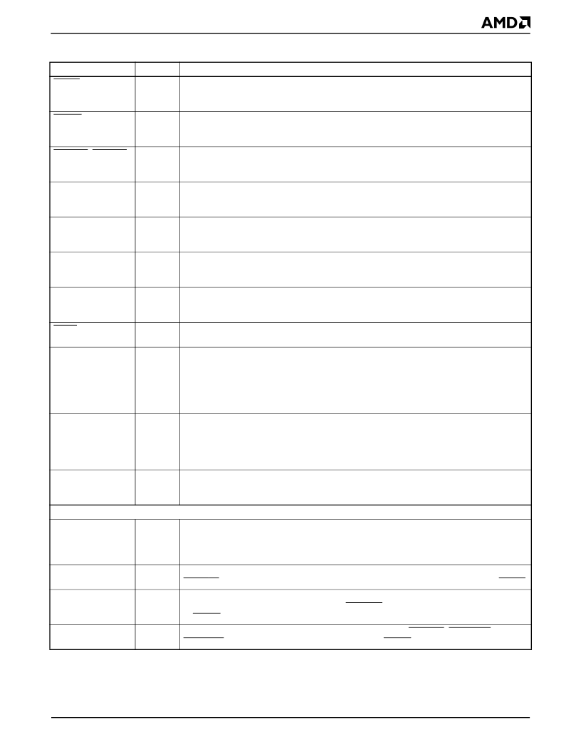
MEMR
O
Memory Read Command
indicates that the current cycle is a read of the currently
addressed memory device. When this signal is asserted, the memory device can drive data
onto the data bus.
Memory Write Command
indicates that the current cycle is a write of the currently
addressed memory device. When this signal is asserted, the memory device can latch data
from the data bus.
Programmable DMA Acknowledge
signals can each be mapped to one of the seven
available DMA channels. They are driven active (Low) back to the DMA initiator to
acknowledge the corresponding DMA requests.
Programmable DMA Requests
can each be mapped to one of the seven available DMA
channels. They are asserted active (High) by a DMA initiator to request DMA service from
the DMA controller.
Programmable Interrupt Requests
can each be mapped to one of the available 8259
interrupt channels. They are asserted when a peripheral requires interrupt service.
(Rising Edge/Active High Trigger)
System Reset
is the ISA bus reset signal. When this signal is asserted, all connected
devices reinitialize to their reset state. This signal should not be confused with the internal
CPU RESET and SRESET signals.
System Address Bus
outputs the physical memory or I/O port latched addresses. It is used
by all external peripheral devices other than main system DRAM. In addition, this is the local
address bus in local bus mode.
System Byte High Enable
is driven active when the high data byte is to be transferred on
the upper 8 bits of the ISA data bus.
System Data Bus
is shared between ISA, 8- or 16-bit ROM/Flash memory, and PC Card
peripherals (on the élanSC400 microcontroller only) and can be directly connected to all of
these devices. In addition, these signals are the upper word of the local data bus, the 32-bit
DRAM interface, and the 32-bit ROM interface. In these modes, the system data bus can be
generated via an external buffer connected to the SD bus and controlled by the buffer control
signals provided.
Speaker, Digital Audio Output
controls an external speaker driver. It is generated from the
internal 8254-compatible timer Channel 2 output ANDed with I/O Port 0061h[1] (Speaker
Data Enable); on the élanSC400 microcontroller, the PC Card speaker signals are
exclusively ORed with each other and the speaker control function of the timer to generate
the SPKR signal.
Terminal Count
is driven from the DMA controller pair to indicate that the transfer count for
the currently active DMA channel has reached zero, and that the current DMA cycle is the
last transfer.
MEMW
O
PDACK1
–PDACK0
O
PDRQ1–PDRQ0
I
PIRQ7–PIRQ0
I
RSTDRV
O
SA25–SA0
O
SBHE
O
SD15–SD0
B
SPKR
O
TC
O
Configuration Pins
BNDSCN_EN
I
Boundary Scan Enable
enables the boundary scan pin functions. When this pin is High, the
boundary scan interface is enabled. When this pin is Low, the boundary scan pin functions
are disabled and the pins are configured to their default functions. This pin must be held Low
during reset for normal operation.
Configuration Pins 1–0
select the data bus width for the physical device(s) selected by the
ROMCS0 pin (i.e., 8-, 16-, or 32-bit-wide). These pins are sampled at the deassertion of RESET.
Configuration Pin 2
selects whether or not the system will boot from PC Card Socket A
memory card or from the device attached to ROMCS0. This pin is sampled at the deassertion
of RESET
. This pin is not supported on the élanSC410 microcontroller.
Configuration Pin 3
enables the SD buffer control signals, DBUFOE, DBUFRDH, and
DBUFRDL. This pin is sampled at the deassertion of RESET.
CFG1–CFG0
I
CFG2
I
CFG3
I
Table 19.
Signal Description Table (Continued)
Signal
Type
Description
相關(guān)PDF資料 |
PDF描述 |
|---|---|
| ELANSC410-100AI | Single-Chip, Low-Power, PC/AT-Compatible Microcontrollers |
| ELANSC410-33AC | Single-Chip, Low-Power, PC/AT-Compatible Microcontrollers |
| ELANSC410-33AI | 5566-12BGS /N/MINI FIT CONN HOUS ASSY |
| ELANSC410-66AC | Single-Chip, Low-Power, PC/AT-Compatible Microcontrollers |
| ELANSC410-66AI | Single-Chip, Low-Power, PC/AT-Compatible Microcontrollers |
相關(guān)代理商/技術(shù)參數(shù) |
參數(shù)描述 |
|---|---|
| ELANSC410-100ACAD | 制造商:Advanced Micro Devices 功能描述: |
| ELANSC410-100AI | 制造商:AMD 制造商全稱:Advanced Micro Devices 功能描述:Single-Chip, Low-Power, PC/AT-Compatible Microcontrollers |
| ELANSC410-33AC | 制造商:Advanced Micro Devices 功能描述:MCU 16-Bit/32-Bit Elan CISC 3.3V 292-Pin BGA |
| ELANSC410-33AI | 制造商:AMD 制造商全稱:Advanced Micro Devices 功能描述:Single-Chip, Low-Power, PC/AT-Compatible Microcontrollers |
| ELANSC410-66AC | 制造商:Advanced Micro Devices 功能描述:MCU 32-bit Elan RISC ROMLess 3.3V 292-Pin BGA 制造商:Advanced Micro Devices 功能描述:MCU 16-Bit/32-Bit Elan CISC 3.3V 292-Pin BGA 制造商:Advanced Micro Devices 功能描述:Microprocessor, 32 Bit, 292 Pin, Plastic, BGA |
發(fā)布緊急采購(gòu),3分鐘左右您將得到回復(fù)。