- 您現(xiàn)在的位置:買(mǎi)賣(mài)IC網(wǎng) > PDF目錄362564 > E1217X (TEMIC SEMICONDUCTORS) 32 KHZ STANDARD WATCH CMOS IC PDF資料下載
參數(shù)資料
| 型號(hào): | E1217X |
| 廠商: | TEMIC SEMICONDUCTORS |
| 元件分類(lèi): | 時(shí)鐘及定時(shí) |
| 英文描述: | 32 KHZ STANDARD WATCH CMOS IC |
| 中文描述: | STEPPING MOTOR WATCH, UUC8 |
| 封裝: | DIE |
| 文件頁(yè)數(shù): | 4/8頁(yè) |
| 文件大?。?/td> | 117K |
| 代理商: | E1217X |
4
e1217X
4728A–CLOCK–06/03
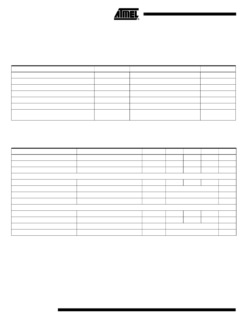
Absolute Maximum Ratings
Absolute maximum ratings define parameter limits which, if exceeded, may permanently change or damage the device.
All inputs and outputs on Atmel’s circuits are protected against electrostatic discharges. However, precautions to minimize
the build-up of electrostatic charges during handling are recommended.
The circuit is protected against supply-voltage reversal for typically 5 minutes.
Parameters
Symbol
Value
Unit
Supply voltage
V
SS
V
IN
-0.3 to +5
V
Input voltage range, all inputs
(V
SS
- 0.3
V)
V
IN
(V
DD
+ 0.3 V)
indefinite
V
Output short-circuit duration
Power dissipation (DIL package)
P
tot
T
amb
T
stg
125
mW
Operating ambient temperature range
-20 to +70
C
Storage temperature range
-40 to +125
C
Lead temperature during soldering at 2 mm
distance, 10 s
T
sld
260
C
Operating Characteristics
V
DD
= 0 V; V
SS
= -1.55 V; T
amb
= +25 C; C
TR
= 15 pF, unless otherwise specified.
All voltage levels are measured with reference to V
DD
. Test crystal as specified below.
Parameters
Test Conditions
Symbol
Min.
Typ.
(1)
Max.
Unit
Operating voltage
Functional test (Figure 2)
V
SS
I
SS
I
R
-1.3
-1.8
V
Operating current
C
oscout
= 16 pF, R
L
= R
RESET = V
DD
-180
-300
nA
RESET input current
Motor Outputs
8
nA
Motor output current
R
L
= 2 k , V
SS
= -1.55 V
I
M
T
M
T
M
T
MT
±0.7
mA
Motor period
See Table 2
s
Motor pulse width
See Table 2
ms
Motor test period
Oscillator
See Table 2
ms
Stability
V
SS
= 100 mV, C
TR
= 5 pF
Startup within 2 s
f/f
0.1
ppm
Start-up voltage
V
ST
-1.3
V
Integrated input capacitor
C
OSC IN
C
OSC OUT
See Table 2
pF
Integrated output capacitor
C
OSCOUTmax
= 24 pF
See Table 2
pF
Note:
1. Typical parameters represent the statistical mean values.
相關(guān)PDF資料 |
PDF描述 |
|---|---|
| E123L | Fixed Inductors for Surface Mounting |
| E130-X10 | Safety transformers |
| E130-X6 | Safety transformers |
| E130-Y7 | Safety transformers |
| E130-Y8 | Safety transformers |
相關(guān)代理商/技術(shù)參數(shù) |
參數(shù)描述 |
|---|---|
| E1217X-B | 制造商:未知廠家 制造商全稱(chēng):未知廠家 功能描述:Watch Circuit |
| E1217X-E | 制造商:未知廠家 制造商全稱(chēng):未知廠家 功能描述:Watch Circuit |
| E1217X-I | 制造商:未知廠家 制造商全稱(chēng):未知廠家 功能描述:Watch Circuit |
| E1217X-S | 制造商:未知廠家 制造商全稱(chēng):未知廠家 功能描述:Watch Circuit |
| E1217X-VA | 制造商:未知廠家 制造商全稱(chēng):未知廠家 功能描述:Watch Circuit |
發(fā)布緊急采購(gòu),3分鐘左右您將得到回復(fù)。