- 您現(xiàn)在的位置:買賣IC網(wǎng) > PDF目錄377005 > DSS72A12B (Electronic Theatre Controls, Inc.) DIP 14 SERIES REED RELAYS PDF資料下載
參數(shù)資料
| 型號(hào): | DSS72A12B |
| 廠商: | Electronic Theatre Controls, Inc. |
| 英文描述: | DIP 14 SERIES REED RELAYS |
| 中文描述: | 雙酯14系列磁簧繼電器 |
| 文件頁(yè)數(shù): | 2/9頁(yè) |
| 文件大小: | 688K |
| 代理商: | DSS72A12B |

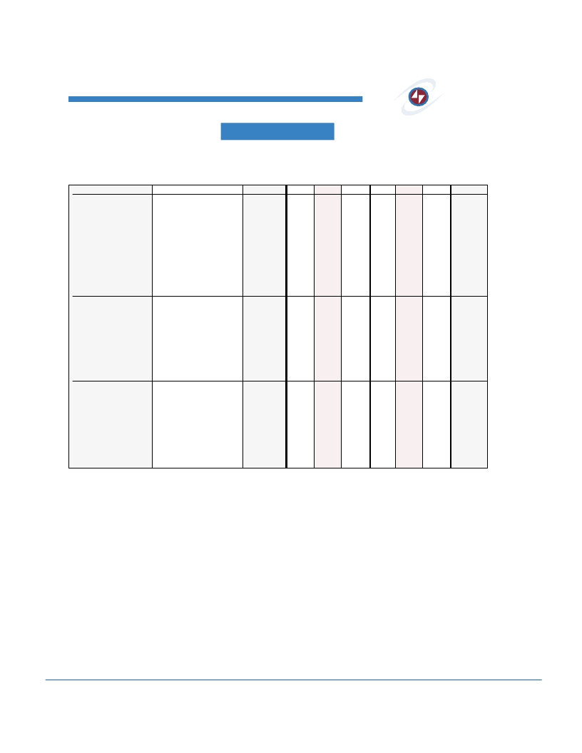
DIP 14 SERIES REED RELAYS
SPECIFICATIONS
MSS2
I
MSS7
I
PRMA
I
DSS7
I
PRME
I
MVS2
I
MVS7
All parameters are at 25°C unless otherwise stated.
Operate voltage, release voltage, and coil resistance will change
approximately 0.4%/°C as ambient temperature varies.
MSS2
Molded 8 Pin
All position
Wetted contacts
MIN
TYP
MSS7
Molded 4 Pin
All position
Wetted contacts
MIN
TYP
PARAMETER
Contact Ratings
Switching Voltage
Switching Current
Carry Current
Contact Rating
Life Expectancy
CONDITIONS
SYMBOL
MAX
MAX
UNITS
Max DC/PeakAC Resistive
Max DC/PeakAC Resistive
Max DC/PeakAC Resistive
Max DC/PeakAC Resistive
Signal Level 1.0 V 10mA
Related Loads
(1)
50mV, 10mA
.5V, 50mA at 100Hz, 1.5 msec
V
L
I
L
I
C
-
-
-
-
-
-
-
-
-
500
2
3
50
-
-
-
-
-
-
-
-
-
-
500
2
3
50
-
Volts
Amps
Amps
Watts
x10
6
Ops
200
200
Static Contact Resistance
Dynamic Contact Resistance
Contact Material
Hg Content
Relay Specifications
Insulation Resistance
CR
DCR
-
-
-
-
40
N/A
Hg
16
100
-
-
-
-
-
-
-
65
N/A
Hg
16
100
-
-
-
m
m
mgrams
Between all isolated pins
at 100V, 25°C, 40% RH
Across Open Contacts
Open Contact to Coil
Between Contacts
Contacts to Coil
At Nominal Coil Voltage
10Hz Square Wave
Zener-Diode Suppression
IR
10
8
10
10
-
10
8
10
10
-
Capacitance
-
1.5
3
-
-
1.2
2
4
-
-
-
-
1.2
3
-
-
1.2
2
4
-
-
pF
pF
Dielectric Strength
1400
1400
-
2000
5600
-
VDC/Peak AC
VDC/Peak AC
ms
I/O
T
OP
Operate Time,
including bounce
Release Time
1.75
1.75
T
REL
-
1
1.50
-
1
1.50
ms
Environmental Ratings
Storage Temperature
Operating Temperature
Soldering Temperature
Vibration Resistance
(Survival)
Shock Resistance
(Survival)
Weight
T
A
T
O
-40
-38
-
-
-
-
+105
+75
-
10
-40
-38
-
-
-
-
+105
+75
°C
°C
°C
Gs
Applied to pins, 5 sec. max.
10Hz - 500Hz
260
-
260
-
G
10
11±1ms,
1
/
2
Sine Wave
S
-
-
30
-
-
30
Gs
-
2.3
-
-
2.3
-
grams
(1)
Refer to life graphs
SRC
DEVICES
2
USA
1-866-SRC-8668
Europe
32
-
89
-
328850
Far East
886
-
2-2698
-
8422
www.srcdevices.com
相關(guān)PDF資料 |
PDF描述 |
|---|---|
| DSS72A12C | DIP 14 SERIES REED RELAYS |
| DSS72A12S | DIP 14 SERIES REED RELAYS |
| DSS72A24A | DIP 14 SERIES REED RELAYS |
| DSS72A24B | DIP 14 SERIES REED RELAYS |
| DSSK16-01A | Power Schottky Rectifier with common cathode |
相關(guān)代理商/技術(shù)參數(shù) |
參數(shù)描述 |
|---|---|
| DSS72A12C | 制造商:未知廠家 制造商全稱:未知廠家 功能描述:DIP 14 SERIES REED RELAYS |
| DSS72A12S | 制造商:未知廠家 制造商全稱:未知廠家 功能描述:DIP 14 SERIES REED RELAYS |
| DSS72A24A | 制造商:未知廠家 制造商全稱:未知廠家 功能描述:DIP 14 SERIES REED RELAYS |
| DSS72A24B | 制造商:未知廠家 制造商全稱:未知廠家 功能描述:DIP 14 SERIES REED RELAYS |
| DSS72A24C | 制造商:未知廠家 制造商全稱:未知廠家 功能描述:DIP 14 SERIES REED RELAYS |
發(fā)布緊急采購(gòu),3分鐘左右您將得到回復(fù)。