- 您現(xiàn)在的位置:買賣IC網(wǎng) > PDF目錄171225 > DS3316P-682MSD (COILCRAFT INC) 1 ELEMENT, 6.8 uH, GENERAL PURPOSE INDUCTOR, SMD PDF資料下載
參數(shù)資料
| 型號: | DS3316P-682MSD |
| 廠商: | COILCRAFT INC |
| 元件分類: | 通用定值電感 |
| 英文描述: | 1 ELEMENT, 6.8 uH, GENERAL PURPOSE INDUCTOR, SMD |
| 文件頁數(shù): | 1/2頁 |
| 文件大?。?/td> | 113K |
| 代理商: | DS3316P-682MSD |
Coilcraft, Inc. 2011
Specifications subject to change without notice.
Please check our website for latest information.
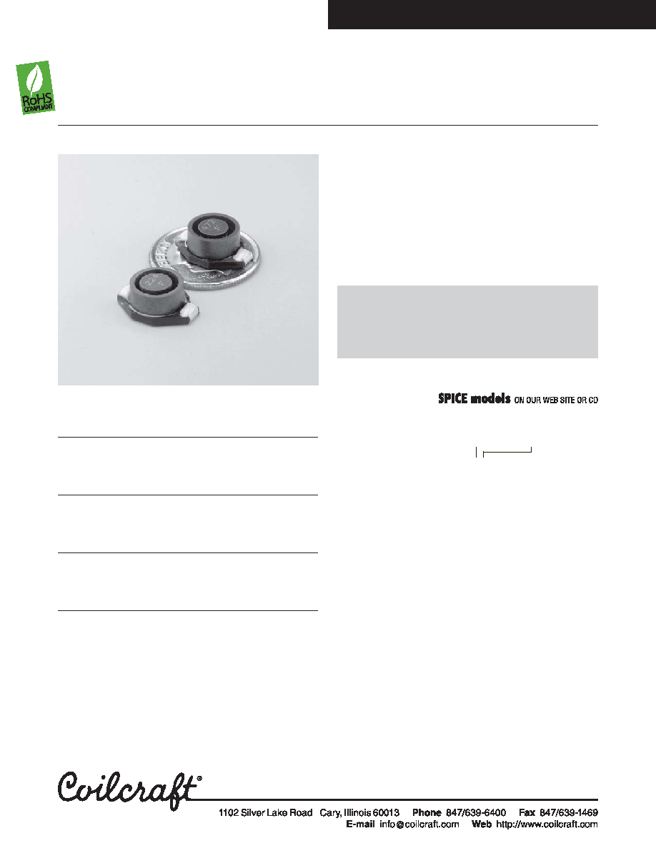
SMTPowerInductors– DS3316PSeries
Magnetic shielding and high efficiency are features of
the DS3316 family of power inductors. They are de-
signed for high performance DC-DC converter applica-
tions, especially those requiring shielding.
The terminations wrap around the end of the base,
ensuring a sound solder fillet and simplifying inspection.
Saturation current ratings up to 11 A and rms current
ratings as high as 5 A are available. DC resistance as
low as 0.021 Ohms keeps power losses to a minimum.
L
DCR
SRF
±20%2
max
typ
Isat3 Irms4
Part number1
(H)
(Ohms)
(MHz)
(A)
DS3316P-102ML_
1.0
0.021
140
11.0
5.0
DS3316P-152ML_
1.5
0.022
120
9.5
4.5
DS3316P-222ML_
2.2
0.032
80
7.8
3.8
DS3316P-332ML_
3.3
0.039
70
6.0
3.3
DS3316P-472ML_
4.7
0.054
40
5.4
2.7
DS3316P-682ML_
6.8
0.075
38
4.5
2.2
DS3316P-822ML_
8.2
0.085
36
4.0
2.1
DS3316P-103ML_
10
0.101
35
3.5
2.0
DS3316P-153ML_
15
0.150
25
3.0
1.5
DS3316P-223ML_
22
0.207
19
2.0
1.3
DS3316P-333ML_
33
0.334
15
1.8
1.1
DS3316P-473ML_
47
0.472
13
1.4
0.80
DS3316P-683ML_
68
0.660
10
1.3
0.70
DS3316P-104ML_
100
1.11
7
1.2
0.60
DS3316P-154ML_
150
1.55
6
0.80
0.50
DS3316P-224ML_
220
2.00
5
0.70
0.37
DS3316P-105ML_
1000
8.30
2
0.32
0.17
Document 187-1
Revised 01/12/11
1. When ordering, please specify termination and packaging codes:
DS3316P-105MLD
Termination: L = RoHS compliant gold over nickel over phos bronze.
Special order: T = RoHS tin-silver-copper (95.5/4/0.5) or
S = non-RoHS tin-lead (63/37).
Packaging:
D =13
″ machine-ready reel. EIA-481 embossed plastic
tape (1000 parts per full reel).
B = Less than full reel. In tape, but not machine ready.
To have a leader and trailer added ($25 charge), use
code letter D instead.
2. Inductance tested at 0.1 Vrms, 100 kHz, 0 Adc.
3. DC current at which the inductance drops 10% (typ) from its value
without current.
4. Current that causes a 40°C temperature rise from 25°C ambient.
5. Ambient temperature range: –40°C to +85°C with
Irms current
+85°C to +125°C with derated current
6. Storage temperature range: Component: –40°C to +125°C
Packaging: –55°C to +80°C
7. Resistance to soldering heat: Three reflows at >217°C for 90 seconds
(+260°C ±5°C for 20 – 40 seconds), allowing parts to cool to room
temperature between.
8. Electrical specifications at 25°C.
See Qualification Standards section for environmental and test data.
Refer to Doc 362 “Soldering Surface Mount Components” before soldering.
For new designs, consider the MSS1038 as an alter-
native to this series. The MSS1038 series is more cost
effective, features a smaller footprint, lower profile, lower
DCR and better current handling. We will continue to
manufacture and support the DS3316 indefinitely.
相關(guān)PDF資料 |
PDF描述 |
|---|---|
| DS3920T-001+T | SPECIALTY ANALOG CIRCUIT, PDSO6 |
| DS52-0002-TR | Low Cost Two-Way SMT Power Divider 1920- 2170 MHz |
| DS52-0004 | Low Cost Two-Way SMT Power Diveder 1510-1660MHz |
| DS52-0004-RTR | Low Cost Two-Way SMT Power Diveder 1510-1660MHz |
| DS52-0004-TR | Low Cost Two-Way SMT Power Diveder 1510-1660MHz |
相關(guān)代理商/技術(shù)參數(shù) |
參數(shù)描述 |
|---|---|
| DS3316P-683ML | 制造商:COILCRAFT 制造商全稱:Coilcraft lnc. 功能描述:SMT Power Inductors |
| DS3316P-683MLD | 制造商:COILCRAFT 制造商全稱:Coilcraft lnc. 功能描述:SMT Power Inductors - DS3316P |
| DS3316P-822ML | 制造商:COILCRAFT 制造商全稱:Coilcraft lnc. 功能描述:SMT Power Inductors |
| DS3316P-822MLD | 制造商:COILCRAFT 制造商全稱:Coilcraft lnc. 功能描述:SMT Power Inductors - DS3316P |
| DS-331PIN | 制造商:MA-COM 制造商全稱:M/A-COM Technology Solutions, Inc. 功能描述:Two-Way Power Divider, 750 - 1500 MHz |
發(fā)布緊急采購,3分鐘左右您將得到回復(fù)。