- 您現(xiàn)在的位置:買賣IC網(wǎng) > PDF目錄10994 > DS2172TN+T&R (Maxim Integrated Products)IC BIT ERROR RATE TESTER 32TQFP PDF資料下載
參數(shù)資料
| 型號: | DS2172TN+T&R |
| 廠商: | Maxim Integrated Products |
| 文件頁數(shù): | 19/22頁 |
| 文件大小: | 0K |
| 描述: | IC BIT ERROR RATE TESTER 32TQFP |
| 產(chǎn)品培訓(xùn)模塊: | Lead (SnPb) Finish for COTS Obsolescence Mitigation Program |
| 標準包裝: | 500 |
| 功能: | 位誤碼率測試器(BERT) |
| 電路數(shù): | 1 |
| 電源電壓: | 4.5 V ~ 5.5 V |
| 電流 - 電源: | 10mA |
| 工作溫度: | -40°C ~ 85°C |
| 安裝類型: | 表面貼裝 |
| 封裝/外殼: | 32-TQFP |
| 供應(yīng)商設(shè)備封裝: | 32-TQFP(7x7) |
| 包裝: | 帶卷 (TR) |
| 其它名稱: | 90-2172T+NTR |
DS2172
6 of 22
2.0 PARALLEL CONTROL INTERFACE
The DS2172 is controlled via a multiplexed bi-directional address/data bus by an external microcontroller
or microprocessor. The DS2172 can operate with either Intel or Motorola bus timing configurations. If
the BTS pin is tied low, Intel timing will be selected; if tied high, Motorola timing will be selected. All
Motorola bus signals are listed in parenthesis (). See the timing diagrams in the A.C. Electrical
Characteristics for more details. The multiplexed bus on the DS2172 saves pins because the address
information and data information share the same signal paths. The addresses are presented to the pins in
the first portion of the bus cycle and data will be transferred on the pins during second portion of the bus
cycle. Addresses must be valid prior to the falling edge of ALE(AS), at which time the DS2172 latches
the address from the AD0 to AD7 pins. Valid write data must be present and held stable during the later
portion of the DS or WR pulses. In a read cycle, the DS2172 outputs a byte of data during the latter
portion of the DS or RD pulses. The read cycle is terminated and the bus returns to a high impedance
state as RD transitions high in Intel timing or as DS transitions low in Motorola timing. The DS2172 can
also be easily connected to non-multiplexed buses. RCLK and TCLK are used to update counters and
load transmit and receive pattern registers. At slow clock rates, sufficient time must be allowed for these
port operations.
3.0 PATTERN SET REGISTERS
The Pattern Set Registers (PSR) are loaded each time a new pattern (whether it be pseudorandom or
repetitive) is to be generated. When a pseudorandom pattern is generated, all four PSRs must be loaded
with FF Hex. When a repetitive pattern is to be created, the four PSRs are loaded with the pattern that is
to be repeated. Please see Tables 4 and 5 for some programming examples.
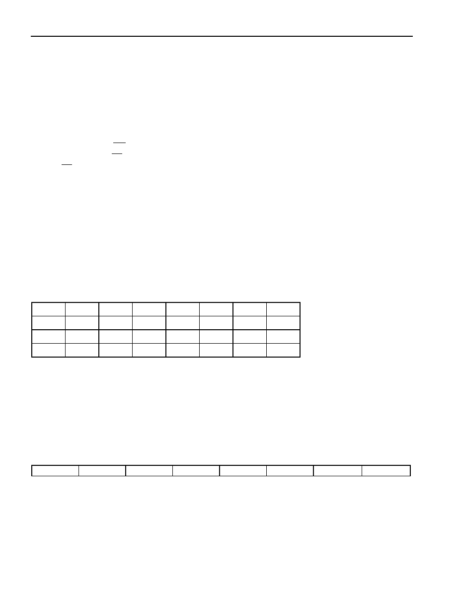
PATTERN SET REGISTERS
(MSB)
(LSB)
PS31
PS30
PS29
PS28
PS27
PS26
PS25
PS24
PSR3 (addr.=00 Hex)
PS23
PS22
PS21
PS20
PS19
PS18
PS17
PS16
PSR2 (addr.=01 Hex)
PS15
PS14
PS13
PS12
PS11
PS10
PS9
PS8
PSR1 (addr.=02 Hex)
PS7
PS6
PS5
PS4
PS3
PS2
PS1
PS0
PSR0 (addr.=03 Hex)
4.0 PATTERN LENGTH REGISTER
Length Bits LB4 to LB0 determine the length of the pseudorandom polynomial or programmable
repetitive pattern that is generated and detected. With the pseudorandom patterns, the “Tap A” feedback
position of the pattern generator is always equal to the value in the Pattern Length Register (PLR). Please
refer to Figure 2 for a block diagram of the pattern generator and to Tables 4 and 5 for some
programming examples.
PLR: PATTERN LENGTH REGISTER (Address=04 Hex)
(MSB)
(LSB)
-
LB4
LB3
LB2
LB1
LB0
相關(guān)PDF資料 |
PDF描述 |
|---|---|
| DS2172TN+ | IC TESTER BIT ERROR RATE 32-TQFP |
| DS2180AQN | IC TRANSCEIVER T1 IND 44-PLCC |
| DS2180AN | IC TRANSCEIVER T1 IND 40-DIP |
| DS2180AQ/T&R | IC TRANSCEIVER T1 44-PLCC |
| DS2180AQ+T&R | IC TRANSCEIVER T1 44-PLCC |
相關(guān)代理商/技術(shù)參數(shù) |
參數(shù)描述 |
|---|---|
| DS2174 | 制造商:MAXIM 制造商全稱:Maxim Integrated Products 功能描述:EBERT |
| DS2174DK | 制造商:未知廠家 制造商全稱:未知廠家 功能描述:Enhanced Bit Error-Rate Tester Design Kit |
| DS2174Q | 功能描述:電信集成電路 Enhanced Bit Error Rate Tester (BERT) RoHS:否 制造商:STMicroelectronics 類型:Telecom IC - Various 工作電源電壓:4.75 V to 5.25 V 電源電流: 工作溫度范圍:- 40 C to + 85 C 安裝風(fēng)格:SMD/SMT 封裝 / 箱體:PQFP-100 封裝:Tray |
| DS2174Q/T&R+ | 制造商:Maxim Integrated Products 功能描述:BIT ERROR RATE TESTER 44PLCC - Tape and Reel |
| DS2174Q/T&R | 功能描述:電信集成電路 RoHS:否 制造商:STMicroelectronics 類型:Telecom IC - Various 工作電源電壓:4.75 V to 5.25 V 電源電流: 工作溫度范圍:- 40 C to + 85 C 安裝風(fēng)格:SMD/SMT 封裝 / 箱體:PQFP-100 封裝:Tray |
發(fā)布緊急采購,3分鐘左右您將得到回復(fù)。