- 您現(xiàn)在的位置:買賣IC網(wǎng) > PDF目錄379178 > DS1245YP-70-IND CAT5E PATCH CORD 50 FOOT BEIGE PDF資料下載
參數(shù)資料
| 型號: | DS1245YP-70-IND |
| 英文描述: | CAT5E PATCH CORD 50 FOOT BEIGE |
| 中文描述: | 1024k非易失SRAM |
| 文件頁數(shù): | 3/12頁 |
| 文件大小: | 221K |
| 代理商: | DS1245YP-70-IND |
DS1245Y/AB
3 of 12
PACKAGES
The DS1245 devices are available in two packages: 32-pin DIP and 34-pin PowerCap Module (PCM).
The 32-pin DIP integrates a lithium battery, an SRAM memory and a nonvolatile control function into a
single package with a JEDEC-standard 600-mil DIP pinout. The 34-pin PowerCap Module integrates
SRAM memory and nonvolatile control along with contacts for connection to the lithium battery in the
DS9034PC PowerCap. The PowerCap Module package design allows a DS1245 PCM device to be
surface mounted without subjecting its lithium backup battery to destructive high-temperature reflow
soldering. After a DS1245 PCM is reflow soldered, a DS9034PC PowerCap is snapped on top of the
PCM to form a complete Nonvolatile SRAM module. The DS9034PC is keyed to prevent improper
attachment. DS1245 PowerCap Modules and DS9034PC PowerCaps are ordered separately and shipped
in separate containers. See the DS9034PC data sheet for further information.
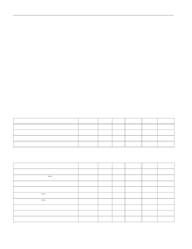
ABSOLUTE MAXIMUM RATINGS*
Voltage on Any Pin Relative to Ground
Operating Temperature
Storage Temperature
Soldering Temperature
-0.3V to +7.0V
0°C to 70°C, -40°C to +85°C for Ind parts
-40°C to +70°C, -40°C to +85°C for Ind parts
260°C for 10 seconds
*
This is a stress rating only and functional operation of the device at these or any other conditions
above those indicated in the operation sections of this specification is not implied. Exposure to
absolute maximum rating conditions for extended periods of time may affect reliability.
RECOMMENDED DC OPERATING CONDITIONS
(t
A
: See Note 10)
PARAMETER
SYMBOL
DS1245AB Power Supply Voltage
V
CC
DS1245Y Power Supply Voltage
V
CC
Logic 1
V
IH
Logic 0
V
IL
MIN
4.75
4.5
2.2
0.0
TYP
5.0
5.0
MAX
5.25
5.5
V
CC
0.8
UNITS
V
V
V
V
NOTES
DC ELECTRICAL
(V
CC
=5V
±
=
5% for DS1245AB)
CHARACTERISTICS
(t
A
: See Note 10) (V
CC
=5V
±
=
10% for DS1245Y)
PARAMETER
SYMBOL
Input Leakage Current
I
IL
I/O Leakage Current
CE
≥
V
IH
≤
V
CC
I
IO
Output Current @ 2.4V
I
OH
Output Current @ 0.4V
I
OL
Standby Current
CE
=2.2V
I
CCS1
Standby Current
CE
=V
CC
-0.5V
I
CCS2
Operating Current
I
CCO1
Write Protection Voltage (DS1245AB)
V
TP
Write Protection Voltage (DS1245Y)
V
TP
MIN
-1.0
-1.0
-1.0
2.0
TYP
MAX
+1.0
+1.0
UNITS
μ
A
μ
A
mA
mA
mA
mA
mA
V
V
NOTES
5.0
3.0
10.0
5.0
85
4.75
4.5
4.50
4.25
4.62
4.37
相關(guān)PDF資料 |
PDF描述 |
|---|---|
| DS1245YP-85-IND | CAT5E PATCH CORD 1 FOOT PINK |
| DS1245Y-85 | 1024k Nonvolatile SRAM |
| DS1245Y-70 | 1024k Nonvolatile SRAM |
| DS1245Y-100 | CABLE SMA/SMA 36 RG-58 |
| DS1245Y-120 | 1024k Nonvolatile SRAM |
相關(guān)代理商/技術(shù)參數(shù) |
參數(shù)描述 |
|---|---|
| DS1245YP-70IND+ | 功能描述:NVRAM 1024K SRAM Nonvolatile RoHS:否 制造商:Maxim Integrated 數(shù)據(jù)總線寬度:8 bit 存儲容量:1024 Kbit 組織:128 K x 8 接口類型:Parallel 訪問時間:70 ns 電源電壓-最大:5.5 V 電源電壓-最小:4.5 V 工作電流:85 mA 最大工作溫度:+ 70 C 最小工作溫度:0 C 封裝 / 箱體:EDIP 封裝:Tube |
| DS1245YP-85 | 制造商:未知廠家 制造商全稱:未知廠家 功能描述:NVRAM (Battery Based) |
| DS1245YP-85-IND | 制造商:DALLAS 制造商全稱:Dallas Semiconductor 功能描述:1024k Nonvolatile SRAM |
| DS-1246ZJ | 制造商:Hikvision USA 功能描述:Outdoor Wall Mount Gooseneck Bracket 制造商:HIKVISION 功能描述:BRACKET WALL MOUNT OUTDOOR GOOSENECK FOR 71XX CAMERAS |
| DS12470W-150# | 制造商:Maxim Integrated Products 功能描述: |
發(fā)布緊急采購,3分鐘左右您將得到回復(fù)。