- 您現(xiàn)在的位置:買(mǎi)賣(mài)IC網(wǎng) > PDF目錄376803 > DM9374N (FAIRCHILD SEMICONDUCTOR CORP) 7-Segment Decoder/Driver/Latch with Constant Current Sink Outputs PDF資料下載
參數(shù)資料
| 型號(hào): | DM9374N |
| 廠商: | FAIRCHILD SEMICONDUCTOR CORP |
| 元件分類(lèi): | 通用總線(xiàn)功能 |
| 英文描述: | 7-Segment Decoder/Driver/Latch with Constant Current Sink Outputs |
| 中文描述: | 93 SERIES, SEVEN SEGMENT DECODER/DRIVER, INVERTED OUTPUT, PDIP16 |
| 封裝: | 0.300 INCH, PLASTIC, MS-001, DIP-16 |
| 文件頁(yè)數(shù): | 6/8頁(yè) |
| 文件大小: | 91K |
| 代理商: | DM9374N |
www.fairchildsemi.com
6
D
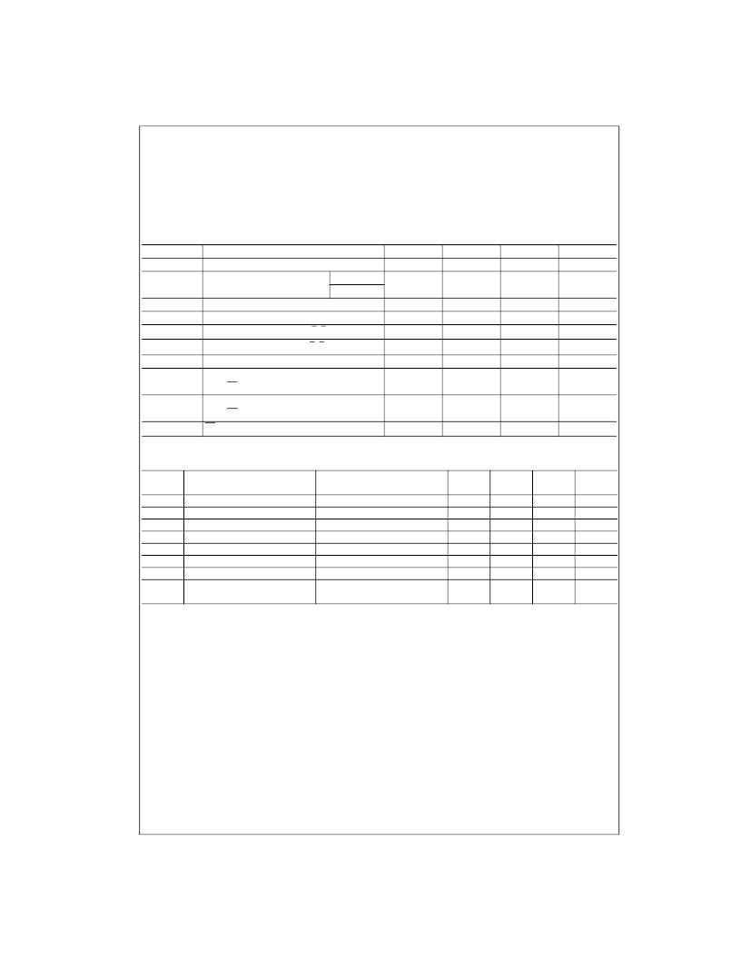
Absolute Maximum Ratings
(Note 3)
Note 3:
The “Absolute Maximum Ratings” are those values beyond which
the safety of the device cannot be guaranteed. The device should not be
operated at these limits. The parametric values defined in the Electrical
Characteristics tables are not guaranteed at the absolute maximum ratings.
The “Recommended Operating Conditions” table will define the conditions
for actual device operation.
Recommended Operating Conditions
Electrical Characteristics
over recommended operating free air temperature range (unless otherwise noted)
Note 4:
All typicals are at V
CC
=
5V, T
A
=
25
°
C.
Note 5:
Not more than one output should be shorted at a time.
Supply Voltage
Input Voltage
Operating Free Air Temperature Range
Storage Temperature Range
7V
5.5V
0
°
C to
+
70
°
C
65
°
C to
+
150
°
C
Symbol
V
CC
V
OUT
Parameter
Min
4.75
Nom
5
Max
5.25
10
Units
V
V
Supply Voltage
Output Voltage Applied
OFF
ON
(Figure 5)
V
IH
V
IL
I
OH
I
OL
T
A
t
S
(H)
t
S
(L)
t
H
(H)
t
H
(L)
t
W
(L)
HIGH Level Input Voltage
LOW Level Input Voltage
HIGH Level Output Current, a
–g, V
OUT
=
5.5V
LOW Level Output Current, a–g, V
OL
=
3.0V
Free Air Operating Temperature
Setup Time HIGH or LOW
An to LE
Hold Time HIGH or LOW
An to LE
2
V
V
μ
A
0.8
250
12
0
75
30
0
0
18
70
mA
°
C
ns
ns
LE Pulse Width LOW
85
ns
Symbol
Parameter
Conditions
Min
Typ
Max
Units
(Note 4)
V
I
V
OH
V
OL
I
I
I
IH
I
IL
I
OS
I
CCH
Input Clamp Voltage
V
CC
=
Min, I
I
=
12 mA
V
CC
=
Min, I
OH
=
Max, V
IL
=
Max
V
CC
=
Min, I
OL
=
Max, V
IH
=
Min
V
CC
=
Max, V
I
=
5.5V
V
CC
=
Max, V
I
=
2.4V
V
CC
=
Max, V
I
=
0.4V
V
CC
=
Max (Note 5)
V
CC
=
Max, V
IN
=
0V,
V
OUT
=
3.0V
1.5
V
HIGH Level Output Voltage
LOW Level Output Voltage
Input Current @ Max Input Voltage
2.4
3.4
0.2
V
V
0.4
1
mA
μ
A
mA
mA
HIGH Level Input Current
LOW Level Input Current
Short Circuit Output Current
40
1.6
57
18
Supply Current
50
mA
相關(guān)PDF資料 |
PDF描述 |
|---|---|
| DM93L14 | Quad Latch(四鎖存器) |
| DM93L14N | Quad Latch |
| DM93L28 | Dual 8-Bit Shift Register(雙8位移位寄存器) |
| DM93L28N | Dual 8-Bit Shift Register |
| DM93L38 | 8-Bit Multiple Port Register(8位多端口寄存器) |
相關(guān)代理商/技術(shù)參數(shù) |
參數(shù)描述 |
|---|---|
| DM9386 | 制造商:NSC 制造商全稱(chēng):National Semiconductor 功能描述:4-Bit Quad Exclusive-NOR with Open-Collector Outputs |
| DM93L00 | 制造商:未知廠家 制造商全稱(chēng):未知廠家 功能描述: |
| DM93L01 | 制造商:未知廠家 制造商全稱(chēng):未知廠家 功能描述: |
| DM93L08 | 制造商:未知廠家 制造商全稱(chēng):未知廠家 功能描述: |
| DM93L09 | 制造商:未知廠家 制造商全稱(chēng):未知廠家 功能描述: |
發(fā)布緊急采購(gòu),3分鐘左右您將得到回復(fù)。