- 您現(xiàn)在的位置:買(mǎi)賣(mài)IC網(wǎng) > PDF目錄376564 > DAC8426AR (ANALOG DEVICES INC) Quad 8-Bit Voltage Out CMOS DAC Complete with Internal 10 V Reference PDF資料下載
參數(shù)資料
| 型號(hào): | DAC8426AR |
| 廠(chǎng)商: | ANALOG DEVICES INC |
| 元件分類(lèi): | DAC |
| 英文描述: | Quad 8-Bit Voltage Out CMOS DAC Complete with Internal 10 V Reference |
| 中文描述: | QUAD, PARALLEL, 8 BITS INPUT LOADING, 3 us SETTLING TIME, 8-BIT DAC, CDIP20 |
| 封裝: | CERDIP-20 |
| 文件頁(yè)數(shù): | 3/12頁(yè) |
| 文件大小: | 289K |
| 代理商: | DAC8426AR |
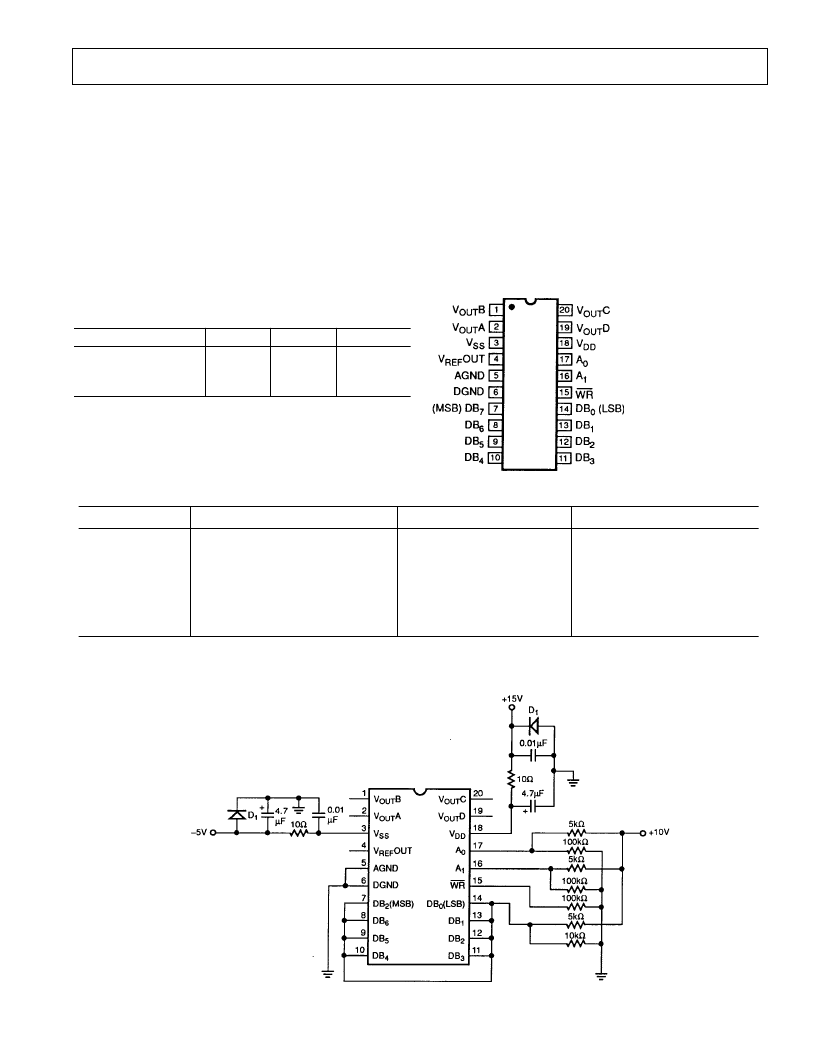
DAC8426
–3–
REV. C
C AUT ION
1. Do not apply voltages higher than V
DD
or less than V
SS
po-
tential on any terminal.
2. T he digital control inputs are zener-protected; however,
permanent damage may occur on unprotected units from
high-energy electrostatic fields. K eep units in conductive
foam at all times until ready to use.
3. Do not insert this device into powered sockets. Remove
power before insertion or removal.
4. Stresses above those listed under “Absolute Maximum Rat-
ings” may cause permanent damage to device.
Burn-In Circuit
ABSOLUT E MAX IMUM RAT INGS
V
DD
to AGND or DGND . . . . . . . . . . . . . . . . .–0.3 V, +17 V
V
SS
to AGND or DGND . . . . . . . . . . . . . . . . . . . . . –7 V, V
DD
V
DD
to V
SS
. . . . . . . . . . . . . . . . . . . . . . . . . . . .–0.3 V, +24 V
AGND to DGND . . . . . . . . . . . . . . . . . . . . . . . .–0.3 V, +5 V
Digital Input Voltage to DGND . . . . . . . . . . . . . –0.3 V, V
DD
V
REF
OUT to AGND
1
. . . . . . . . . . . . . . . . . . . . . –0.3 V, V
DD
V
OUT
to AGND
1
. . . . . . . . . . . . . . . . . . . . . . . . . . . . V
SS
, V
DD
Operating T emperature
Military AR/BR . . . . . . . . . . . . . . . . . . . . –55
°
C to +125
°
C
Extended Industrial ER/EP/FR/FP/FS . . . . –40
°
C to +85
°
C
Maximum Junction T emperature . . . . . . . . . . . . . . . . +150
°
C
Storage T emperature . . . . . . . . . . . . . . . . . . –65
°
C to +150
°
C
Lead T emperature (Soldering, 60 sec) . . . . . . . . . . . . +300
°
C
T HE RMAL RE SIST ANCE
Package T ype
20-Pin Cerdip (R)
20-Pin Plastic DIP (P)
20-Pin SOL(S)
u
JA2
70
61
80
u
JC
7
24
22
Units
°
C/W
°
C/W
°
C/W
NOT ES
1
Outputs may be shorted to any terminal provided the package power dissipation
is not exceeded. T ypical output short-circuit current to AGND is 50 mA.
2
θ
is specified for worst case mounting conditions, i.e.,
θ
is specified for de-
vice in socket for cerdip and P-DIP packages;
θ
JA
is specified for device sol-
dered to printed circuit board for SOL package.
20-Pin Cerdip
(R Suffix)
20-Pin E poxy DIP
(P Suffix)
20-Pin SOL
(S Suffix)
PIN CONNE CT IONS
ORDE RING GUIDE
1
Model
T otal Unadjusted E rror
T emperature Range
Package Description
DAC8426AR
2
DAC8426ER
DAC8426EP
DAC8426BR
2
DAC8426FR
DAC8426FP
DAC8426FS
3
NOT ES
1
Burn-in is available on commercial and industrial temperature range parts in cerdip, plastic DIP, and T O-can packages.
2
For devices processed in total compliance to MIL-ST D-883, add /883 after part number. Consult factory for 883 data sheet.
3
For availability and burn-in information on SO and PLCC packages, contact your local sales office.
±
1 LSB
±
1 LSB
±
1 LSB
±
2 LSB
±
2 LSB
±
2 LSB
±
2 LSB
–55
°
C to +125
°
C
–40
°
C to +85
°
C
–40
°
C to +85
°
C
–55
°
C to +125
°
C
–40
°
C to +85
°
C
–40
°
C to +85
°
C
–40
°
C to +85
°
C
20-Pin Cerdip (Q-20)
20-Pin Cerdip (Q-20)
20-Pin Plastic DIP (N-20)
20-Pin Cerdip (Q-20)
20-Pin Cerdip (Q-20)
20-Pin Plastic DIP (N-20)
20-Lead SOL (R-20)
相關(guān)PDF資料 |
PDF描述 |
|---|---|
| DAC8426BR | Quad 8-Bit Voltage Out CMOS DAC Complete with Internal 10 V Reference |
| DAC8426EP | Quad 8-Bit Voltage Out CMOS DAC Complete with Internal 10 V Reference |
| DAC8426ER | Quad 8-Bit Voltage Out CMOS DAC Complete with Internal 10 V Reference |
| DAC8426FP | Quad 8-Bit Voltage Out CMOS DAC Complete with Internal 10 V Reference |
| DAC8426FR | Quad 8-Bit Voltage Out CMOS DAC Complete with Internal 10 V Reference |
相關(guān)代理商/技術(shù)參數(shù) |
參數(shù)描述 |
|---|---|
| DAC8426AR/883 | 制造商:未知廠(chǎng)家 制造商全稱(chēng):未知廠(chǎng)家 功能描述:8-Bit Digital-to-Analog Converter |
| DAC8426AR/883C | 功能描述:數(shù)模轉(zhuǎn)換器- DAC COMPLETE QUAD 8-BIT DAC-LEV.B RoHS:否 制造商:Texas Instruments 轉(zhuǎn)換器數(shù)量:1 DAC 輸出端數(shù)量:1 轉(zhuǎn)換速率:2 MSPs 分辨率:16 bit 接口類(lèi)型:QSPI, SPI, Serial (3-Wire, Microwire) 穩(wěn)定時(shí)間:1 us 最大工作溫度:+ 85 C 安裝風(fēng)格:SMD/SMT 封裝 / 箱體:SOIC-14 封裝:Tube |
| DAC8426BR | 制造商:Rochester Electronics LLC 功能描述:- Bulk |
| DAC8426BR/883 | 制造商:未知廠(chǎng)家 制造商全稱(chēng):未知廠(chǎng)家 功能描述:8-Bit Digital-to-Analog Converter |
| DAC8426BR/883C | 制造商:Rochester Electronics LLC 功能描述:- Bulk |
發(fā)布緊急采購(gòu),3分鐘左右您將得到回復(fù)。