- 您現(xiàn)在的位置:買賣IC網(wǎng) > PDF目錄378466 > CXA1597P (Sony Corporation) Recording Equalizer Amplifier for Stereo Cassette Decks(立體聲盒式錄音機錄音均衡器) PDF資料下載
參數(shù)資料
| 型號: | CXA1597P |
| 廠商: | Sony Corporation |
| 英文描述: | Recording Equalizer Amplifier for Stereo Cassette Decks(立體聲盒式錄音機錄音均衡器) |
| 中文描述: | 錄制立體聲放大器均衡盒式橋面(立體聲盒式錄音機錄音均衡器) |
| 文件頁數(shù): | 10/22頁 |
| 文件大?。?/td> | 296K |
| 代理商: | CXA1597P |
– 10 –
CXA1597M/P
Description of Operation
1. Recording equalizer amplifier
The primary features of the CXA1597 recording equalizer amplifier are that by taking full advantage of
monolithic filter technology, an LC resonance circuit consisting of a coil and capacitor normally required for
high frequency compensation is dispensed with and medium and low-frequency sensitivity compensation is
performed with its internal filter alone.
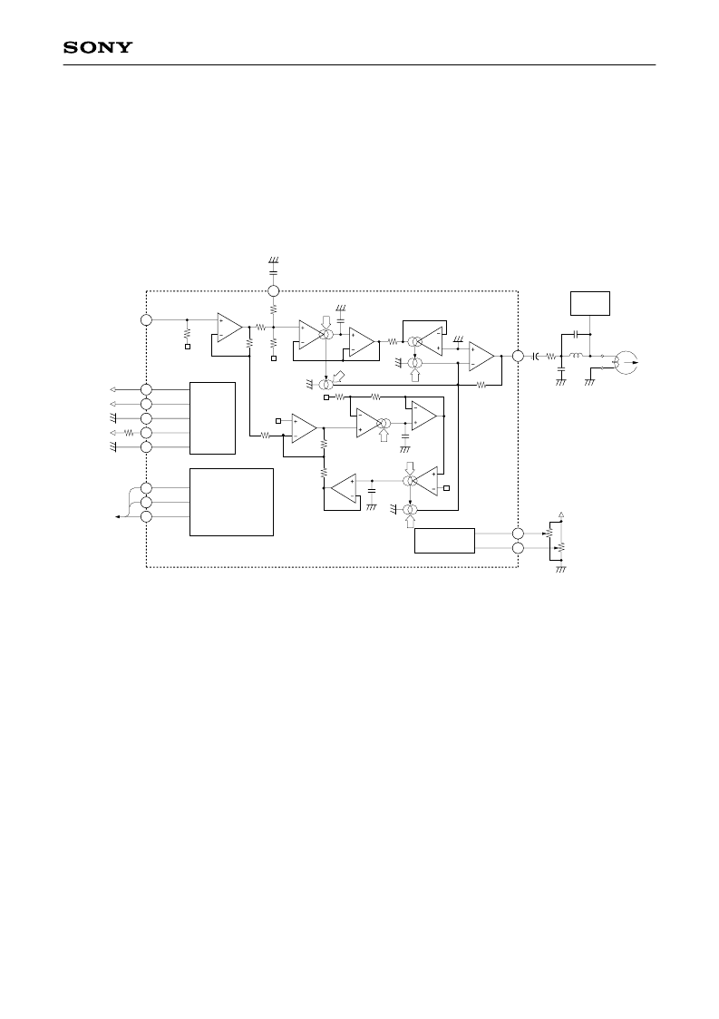
This IC has the circuit configuration shown in Fig. 1 to provide the optimum frequency response required for
recording equalizer amplifiers.
2L1
G
G
E
GND
GND
R1
V
C
V
E
Gm3
×
1
×
1
Gm2
Gm5
OP4
×
1
OP3
OP2
VGS
R7
VGS
R3
R8
4.8k
–7dBv
0C1
GND
2C2
R4
40k
GND
R13
50k
R9
8k
1C4
GND
C3
100p
G
R5
R6
20k
R2
5k
V
V
G
G
Gm4
V
BIAS
CONTROL
–6dBv
–6dBv
+
REC OUT
–7dBv
0dBv
REC IN
V
CC
V
EE
GND (VG)
IREF
DGND
TAPE EQ
REC MUTE
SPEED
to Control IC
R1 27k
GND
GND
REC HEAD
Bias
C7
12k
C5
3.3μ
C6
150p
GND
REC CAL
CALIBRATION
Gp CAL
DV
CC
50k
50k
BOOST
IfM
IGL
IGH
If/Q
IfQ
IGP
Fig. 1. CXA1597 functional circuit block diagram
The symbols (Gm2, Gm3, Gm4, Gm5) shown in Fig. 1 denote "voltage
→
current converter circuits" and
"multiplier circuits."
The "voltage
→
current converter circuits" convert the voltage between the positive and negative input pins into
current by using the IC's internal resistance. The "multiplier circuits" multiply the current generated by the
"voltage
→
current converter circuits" with a coefficient.
The recording equalizer amplifier requires the six parameters shown in Fig. 2 (G
L
, G
H
, G
P
, f
M
, f
P
, and Q) to
implement its frequency response. These parameters are controlled by each control current shown in Fig. 1
(IGL, IGH, IGP, IfM, If/Q, and IfQ).
Therefore, the CXA1597 reduces fluctuations caused by the temperature characteristics and unevenness of its
internal resistance by using currents which are independent of the internal resistance (currents which depend
on external resistance) and those which are dependent on the internal resistance.
This IC uses currents dependent on the internal resistance where equalizer amplifier gain is determined and
currents dependent on external resistance where the filter time constant is determined. This is because the
generatrix of the coefficient for the "multiplier circuits" is generated in the IC so that it depends on the internal
resistance. Consequently, the gain relationship of G
L
, G
H
and G
P
is such that because the current obtained by
the "voltage
→
current converter circuits" is converted into voltage by the I-V amplifier in the final stage of Fig.
1, the control currents are controlled by currents dependent on the internal resistance. In this way, the
coefficients for conversion [voltage
→
current
→
voltage] all become ratios to the internal resistance, so that
the fluctuations of temperature characteristics and unevenness are reduced.
相關(guān)PDF資料 |
PDF描述 |
|---|---|
| CXA1598M | Recording Equalizer Amplifier for Stereo Cassette Decks(立體聲盒式錄音機錄音均衡放大器) |
| CXA1598S | Recording Equalizer Amplifier for Stereo Cassette Decks(立體聲盒式錄音機錄音均衡放大器) |
| CXA1598 | Recording Equalizer Amplifier for Stereo Cassette Decks |
| CXA1599Q | 1-Chip Cassette Deck IC(單片盒式錄音機芯片) |
| CXA1635 | STEREO PRE-AMPLIFIER/POWER-AMPLIGIER WITH 3V GOVERNOR |
相關(guān)代理商/技術(shù)參數(shù) |
參數(shù)描述 |
|---|---|
| CXA1598 | 制造商:SONY 制造商全稱:Sony Corporation 功能描述:Recording Equalizer Amplifier for Stereo Cassette Decks |
| CXA1598M | 制造商:SONY 制造商全稱:Sony Corporation 功能描述:Recording Equalizer Amplifier for Stereo Cassette Decks |
| CXA1598M/S | 制造商:未知廠家 制造商全稱:未知廠家 功能描述:Recording Equalizer Amplifier for Stereo CassetteDecks |
| CXA1598S | 制造商:SONY 制造商全稱:Sony Corporation 功能描述:Recording Equalizer Amplifier for Stereo Cassette Decks |
| CXA1599Q | 制造商:SONY 制造商全稱:Sony Corporation 功能描述:1-chip Cassette Deck |
發(fā)布緊急采購,3分鐘左右您將得到回復(fù)。