- 您現(xiàn)在的位置:買賣IC網(wǎng) > PDF目錄170207 > CS8414 (Electronic Theatre Controls, Inc.) 96 KHZ DIGITAL AUDIO RECEIVER PDF資料下載
參數(shù)資料
| 型號: | CS8414 |
| 廠商: | Electronic Theatre Controls, Inc. |
| 英文描述: | 96 KHZ DIGITAL AUDIO RECEIVER |
| 中文描述: | 96 kHz的數(shù)字音頻接收器 |
| 文件頁數(shù): | 16/38頁 |
| 文件大?。?/td> | 646K |
| 代理商: | CS8414 |
第1頁第2頁第3頁第4頁第5頁第6頁第7頁第8頁第9頁第10頁第11頁第12頁第13頁第14頁第15頁當(dāng)前第16頁第17頁第18頁第19頁第20頁第21頁第22頁第23頁第24頁第25頁第26頁第27頁第28頁第29頁第30頁第31頁第32頁第33頁第34頁第35頁第36頁第37頁第38頁
CS8413 CS8414
DS240F1
23
leaving the reset state. The CS8414 should be reset
immediately after power-up and any time the user
performs a system-wide reset. See Appendix B for
a suggested reset circuit.
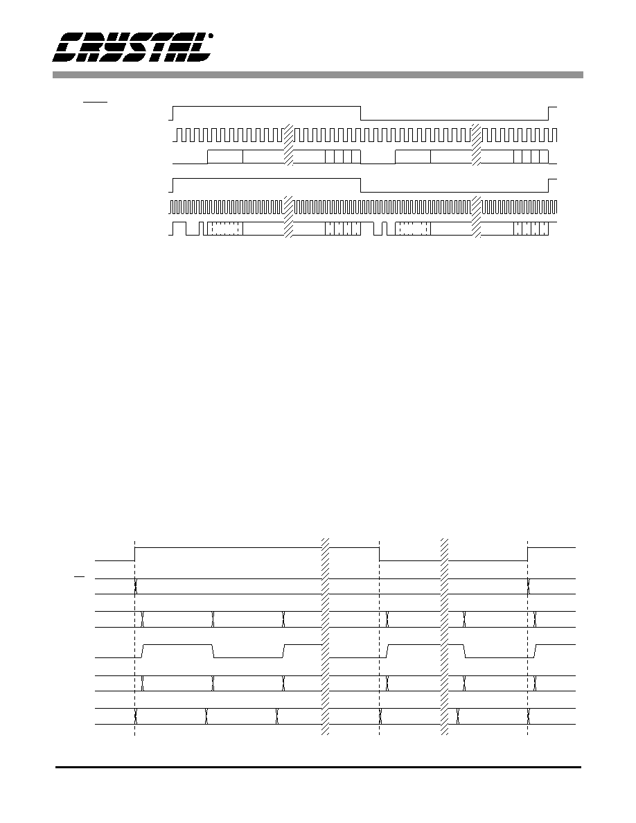
C, U, VERF, ERF, and CBL Serial Outputs
The C and U bits and CBL are output one SCK pe-
riod prior to the active edge of FSYNC in all serial
port formats except 2 and 3 (I2S modes). The active
edge of FSYNC may be used to latch C, U, and
CBL externally. In formats 2 and 3, the C and U
bits and CBL are updated with the active edge of
FSYNC. The validity + error flag (VERF) and the
error flag (ERF) are always updated at the active
edge of FSYNC. This timing is illustrated in
Figure 19.
The C output contains the channel status bits with
CBL rising indicating the start of a new channel
status block. CBL is high for the first four bytes of
channel status (32 frames or 64 samples) and low
for the last 20 bytes of channel status (160 frames
or 320 samples). The U output contains the User
Channel data. The V bit is OR’ed with the ERF flag
and output on the VERF pin. This indicates that the
audio sample may be in error and can be used by in-
terpolation filters to interpolate through the error.
ERF being high indicates a serious error occurred
on the transmission line. There are three errors that
cause ERF to go high: a parity error or biphase cod-
ing violation during that sample, or an out of lock
PLL receiver. Timing for the above pins is illustrat-
ed in Figure 19.
No.
FSYNC (out)
SDATA (out)
13*
FSYNC (out)
SCK (out)
SDATA (out)
12*
MSB VU CP
LSB
AUX
MSB VU C P
LSB
AUX
Left
Right
Left
Right
VU CP
LSB
VU C P
LSB
SCK (out)
MSB
AUX
* Error flags are not accurate in these modes
Figure 18. Special Audio Port Formats 12 and 13
CBL
SDATA
FSYNC
Left 0
Left 1
Right 0
Left 0
Left 32
Right 191
Right 31
Right 191
C0,
Ca-Ce
ERF,
VERF
C, U
Figure 19. CBL Timing
相關(guān)PDF資料 |
PDF描述 |
|---|---|
| CS8414-CS | 96 KHZ DIGITAL AUDIO RECEIVER |
| CSB7152-01 | 70 V, SILICON, PIN DIODE |
| CSBFB1M00J58-R1 | CERAMIC RESONATOR, 1 MHz |
| CSBLA400KECE-B0 | CERAMIC RESONATOR, 0.4 MHz |
| CSC09ST-224K-B246 | 1 ELEMENT, 220000 uH, GENERAL PURPOSE INDUCTOR |
相關(guān)代理商/技術(shù)參數(shù) |
參數(shù)描述 |
|---|---|
| CS8414CS | 制造商:CRYS 功能描述: 制造商:The Cherry Corporation 功能描述: |
| CS8414-CS | 制造商:Rochester Electronics LLC 功能描述: 制造商:Cirrus Logic 功能描述: |
| CS8414-CSR | 制造商:Rochester Electronics LLC 功能描述: 制造商:Cirrus Logic 功能描述: |
| CS8414-CSZ | 功能描述:音頻 DSP IC 96 kHz Digital Audio Receivers RoHS:否 制造商:Texas Instruments 工作電源電壓: 電源電流: 工作溫度范圍: 安裝風(fēng)格: 封裝 / 箱體: 封裝:Tube |
| CS8414-CSZ/A | 制造商:Cirrus Logic 功能描述: |
發(fā)布緊急采購,3分鐘左右您將得到回復(fù)。