- 您現(xiàn)在的位置:買賣IC網(wǎng) > PDF目錄170207 > CS3845GDR8 (ON SEMICONDUCTOR) 1 A SWITCHING CONTROLLER, PDSO8 PDF資料下載
參數(shù)資料
| 型號: | CS3845GDR8 |
| 廠商: | ON SEMICONDUCTOR |
| 元件分類: | 穩(wěn)壓器 |
| 英文描述: | 1 A SWITCHING CONTROLLER, PDSO8 |
| 封裝: | SO-8 |
| 文件頁數(shù): | 6/12頁 |
| 文件大小: | 158K |
| 代理商: | CS3845GDR8 |
CS2844, CS3844, CS2845, CS3845
http://onsemi.com
3
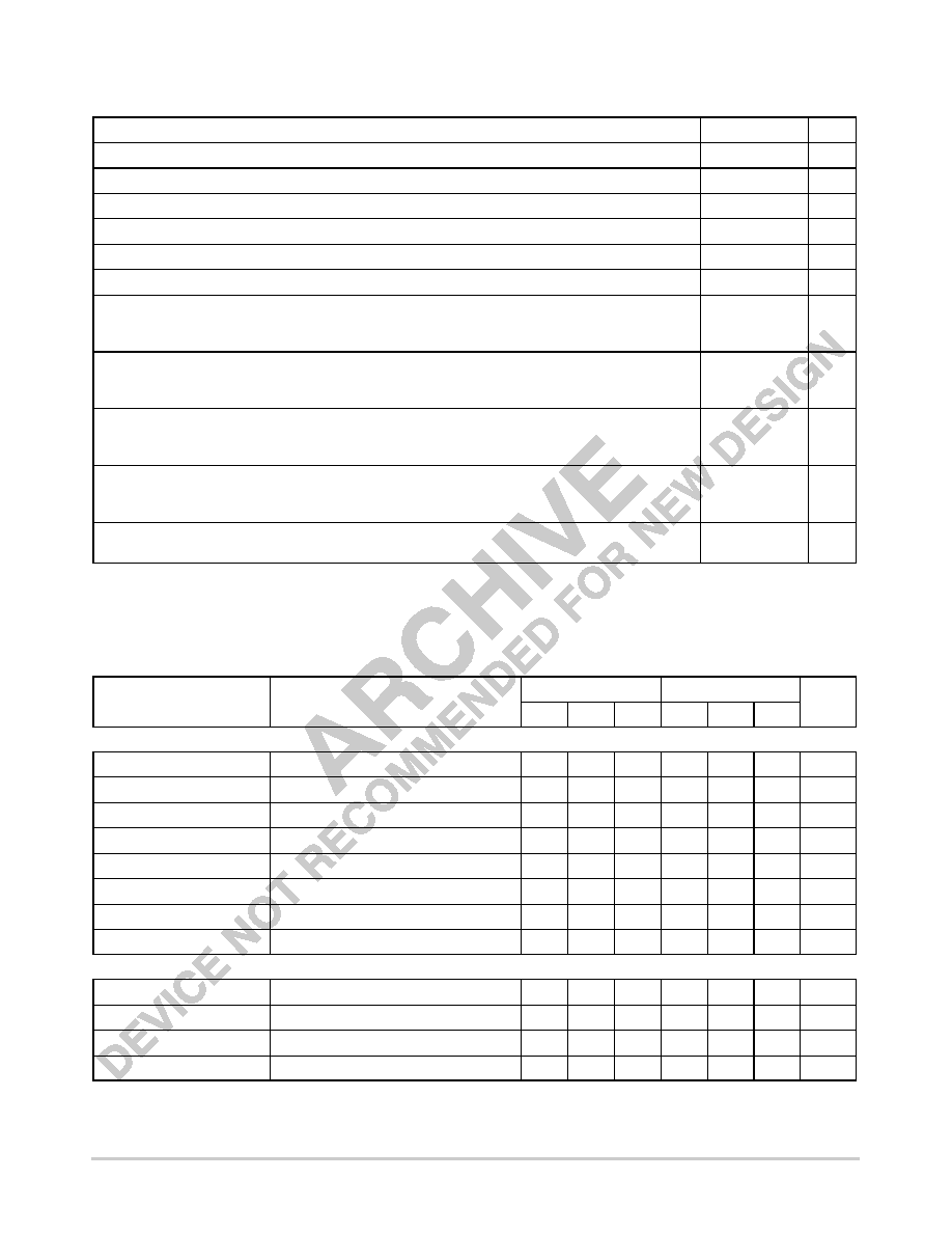
MAXIMUM RATINGS*
Rating
Value
Unit
Supply Voltage (ICC < 30 mA)
Self Limiting
–
Supply Voltage (Low Impedance Source)
30
V
Output Current
±1.0
A
Output Energy (Capacitive Load)
5.0
J
Analog Inputs (VFB, Sense)
–0.3 to + 5.5
V
Error Amp Output Sink Current
10
mA
Package Thermal Resistance, PDIP–8
Junction–to–Case, RθJC
Junction–to–Ambient, RθJA
52
100
°CW
Package Thermal Resistance, SO–8
Junction–to–Case, RθJC
Junction–to–Ambient, RθJA
45
165
°CW
Package Thermal Resistance, SO–14
Junction–to–Case, RθJC
Junction–to–Ambient, RθJA
30
125
°CW
Package Thermal Resistance, SO–16L
Junction–to–Case, RθJC
Junction–to–Ambient, RθJA
23
105
°CW
Lead Temperature Soldering:
Wave Solder (through hole styles only) (Note 1)
Reflow (SMD styles only) (Note 2)
260 peak
230 peak
°C
1. 10 second maximum.
2. 60 second maximum above 183
°C.
*The maximum package power dissipation must be observed.
ELECTRICAL CHARACTERISTICS (–25
° ≤ TA ≤ 85° for CS2844/2845, 0° ≤ TA ≤ 70° for CS3844/CS3845.
VCC = 15 V*; RT = 10 k, CT = 3.3 nF for sawtooth mode; unless otherwise stated.)
CS2844/CS2845
CS3844/CS3845
Characteristic
Test Conditions
Min
Typ
Max
Min
Typ
Max
Unit
Reference Section
Output Voltage
TJ = 25°C, IREF = 1.0 mA
4.95
5.00
5.05
4.90
5.00
5.10
V
Line Regulation
12
≤ VCC ≤ 25 V
–
6.0
20
–
6.0
20
mV
Load Regulation
1.0
≤ IREF ≤ 20 mA
–
6.0
25
–
6.0
25
mV
Temperature Stability
Note 3.
–
0.2
0.4
–
0.2
0.4
mV/
°C
Total Output Variation
Line, Load, Temperature. Note 3.
4.90
–
5.10
4.82
–
5.18
V
Output Noise Voltage
10 Hz
≤ f ≤ 10 kHz, TJ = 25°C. Note 3.
–
50
–
50
–
V
Long Term Stability
TA = 125°C, 1000 Hrs. Note 3.
–
5.0
25
–
5.0
25
mV
Output Short Circuit
TA = 25°C
–30
–100
–180
–30
–100
–180
mA
Oscillator Section
Initial Accuracy
Sawtooth Mode, TJ = 25°C
47
52
57
47
52
57
kHz
Voltage Stability
12
≤ VCC ≤ 25 V
–
0.2
1.0
–
0.2
1.0
%
Temperature Stability
Sawtooth Mode TMIN ≤ TA ≤ TMAX. Note 3.
–
5.0
–
5.0
–
%
Amplitude
VOSC (peak to peak)
–
1.7
–
1.7
–
V
3. These parameters, although guaranteed, are not 100% tested in production.
*Adjust VCC above the start threshold before setting at 15 V.
相關(guān)PDF資料 |
PDF描述 |
|---|---|
| CS51023D16 | 1 A SWITCHING CONTROLLER, 1000 kHz SWITCHING FREQ-MAX, PDSO16 |
| CS5124XDR8 | 1.5 A SWITCHING CONTROLLER, 440 kHz SWITCHING FREQ-MAX, PDSO8 |
| CS5322GDWR28 | 1.5 A SWITCHING CONTROLLER, 1000 kHz SWITCHING FREQ-MAX, PDSO28 |
| CS5361GD16 | 2 A BATTERY CHARGE CONTROLLER, 635 kHz SWITCHING FREQ-MAX, PDSO16 |
| CS8413 | 96 KHZ DIGITAL AUDIO RECEIVER |
相關(guān)代理商/技術(shù)參數(shù) |
參數(shù)描述 |
|---|---|
| CS3845GDW16 | 制造商:CHERRY 制造商全稱:CHERRY 功能描述:Current Mode PWM Control Circuit with 50% Max Duty Cycle |
| CS3845GDWR16 | 制造商:CHERRY 制造商全稱:CHERRY 功能描述:Current Mode PWM Control Circuit with 50% Max Duty Cycle |
| CS3845GN8 | 制造商:Rochester Electronics LLC 功能描述:- Bulk |
| CS-3845N8 | 制造商:未知廠家 制造商全稱:未知廠家 功能描述:Current-Mode SMPS Controller |
| CS-386 | 制造商:未知廠家 制造商全稱:未知廠家 功能描述:Automotive Voltage Regulator |
發(fā)布緊急采購,3分鐘左右您將得到回復(fù)。