- 您現(xiàn)在的位置:買賣IC網(wǎng) > PDF目錄382907 > CONFERENCEPAPERREPRINT Conference Paper Reprint - Multimedia over FDDI (Paper) PDF資料下載
參數(shù)資料
| 型號: | CONFERENCEPAPERREPRINT |
| 英文描述: | Conference Paper Reprint - Multimedia over FDDI (Paper) |
| 中文描述: | 會議文件再版-在FDDI(多媒體文件) |
| 文件頁數(shù): | 7/28頁 |
| 文件大?。?/td> | 120K |
| 代理商: | CONFERENCEPAPERREPRINT |
第1頁第2頁第3頁第4頁第5頁第6頁當前第7頁第8頁第9頁第10頁第11頁第12頁第13頁第14頁第15頁第16頁第17頁第18頁第19頁第20頁第21頁第22頁第23頁第24頁第25頁第26頁第27頁第28頁
6: Use of FDDI Synchronous class of service
for video/voice applications
The purpose of our study was to examine the feasibility
of multimedia applications over the FDDI synchronous
channel when the FDDI is shared with normal, bursty data
traffic. The synchronous channel offers a protected, low-
latency bandwidth, which when unused is available to the
normal asynchronous transmissions.
A portion of the FDDI bandwidth is allocated to
synchronous services, either at startup or later by a
bandwidth allocater. Up to 100% of the network
bandwidth can be allocated to the synchronous service. In
other words, it is possible to implement a synchronous
only network. This allocation can be fixed, dynamically
allocated at session initiation, or on any granularity
preferred by the network administrator. A standard
allocator such as CCITT Q.931, may be used to perform
call-setup, tear-down and bandwidth allocation and
monitoring. SMT defines a protocol and several MIB
attributes which can be used to monitor and control the
bandwidth allocation [27].
Each multimedia station is allocated a portion of the
synchronous bandwidth. In order to allocate the
bandwidth, each station needs to characterize the
application requirements in terms of overhead and
payload, where overhead includes token capture, framing
and higher layer protocol headers, and payload is the
actual synchronous data (e.g. voice, video). This should
be calculated in units of bytes per 125 microseconds. An
application of 1.5 Mbps would require 1.5 x 106 x 125 x
10-6 /8= 23.4375 rounded up to 24 units of bandwidth. A
similar calculation should be done for the overhead. The
total bandwidth available is of the order of 100 x 106 x
125 x 10-6 /8 = 1562 units. Following the bandwidth
allocation, it is necessary to select the packet sizes for the
negotiated TTRT. For example, with a TTRT of 8 ms, the
packet size for the above synchronous traffic (1.5 Mbps
stream) can be calculated as the number of bytes that the
stream will produce in 8 ms. This is 1500 bytes. Hence,
with an 8 ms TTRT, and a 1.5 Mbps video stream, 1500
byte packets will be transmitted per token rotation.
The above method of allocating bandwidth was
selected so that an application would not have to change
bandwidth allocation every time that the TTRT value
changed. Only the packet size would change while
maintaining a constant overhead. There are other
mechanisms for allocating bandwidth which may be
simpler and more suitable for different network
configurations.
For the purposes of the simulation we allocated
synchronous bandwidth based on the TTRT value. Thus
an 8 ms TTRT with a 1.5 Mbps application would require
1500 byte transmission time or 1500 x 80 ns = 0.12 ms per
TTRT.
7: Network operation
An FDDI network can be operated in three ways:
1] asynchronous only;
2] mixed asynchronous and synchronous;
3] synchronous only.
We decided to test the network in all modes of
operation with a special emphasis on the mixed
asynchronous and synchronous mode. The offered
network load was varied from 80% to about 150% of
capacity. The traffic was a mixture of various applications
such as voice, video, imaging, file servers, and interactive
data.
We wanted to test the network not for its maximum
configurations but for its typical configurations. After
conducting a survey of the existing implementations and
practices, we concluded that a maximum
unsegmented
network was in the range of 40-60 nodes. An
unsegmented network has nodes on the same physical
cable-plant with no intervening bridges, routers or some
such interworking units. Usually, networks do not exceed
50 nodes because of issues such as loading, administrative
domains, and traffic isolation. We selected a network
with nodes in the range of 48 to 55 as the representative
maximum of the typical network.
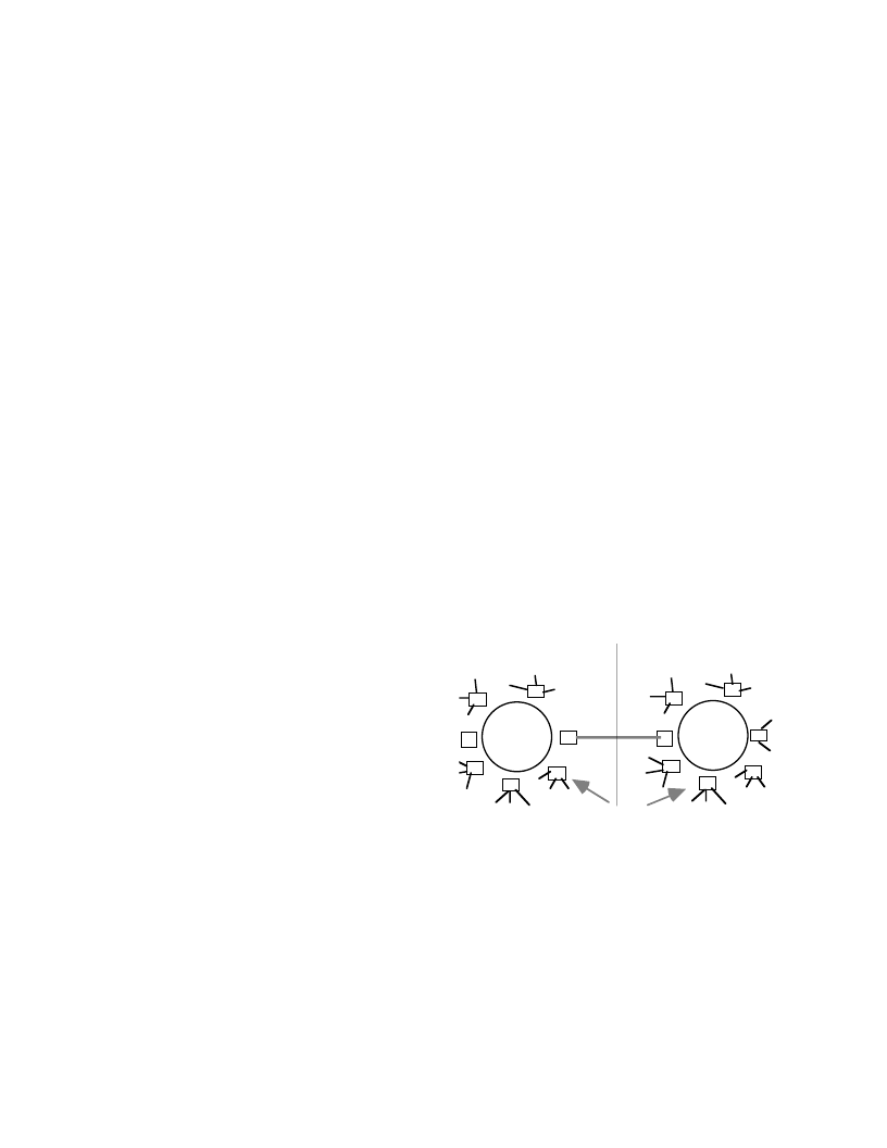
7.1 Topology
The following topology was adopted as the model for
the study. A LAN-WAN-LAN model was seen as
appropriate for typical multimedia services. We assumed
that the two LANs were symmetrical in behavior.
WAN
FDDI
FDDI
concentrator/
station
Figure 3: Topology for simulation
A single hierarchy of connections was selected because
of the linearity of each LAN segment. Therefore, the
delay characteristics for a single LAN could be linearly
scaled to represent multiple-level LAN hierarchy. The
WAN connection was assumed to offer a fixed latency
path. The WAN could consist of ISDN, fractional T1, T1
or T3 lines depending on the bandwidth required.
7.2: Ring latency
相關(guān)PDF資料 |
PDF描述 |
|---|---|
| CONFIGURE | Configure Low-Cost Buck Controller for Boost Operation (21k) |
| CONFIGURING | Configuring the ?lanSC300 Device's Internal CGA Controller for a Specific LCD Panel Application Note? 277KB (PDF) |
| CONTROLINTEGRATEDCIRCUITS | Control Integrated Circuits(22.16 k) |
| COREWARE | CoreWare Merlin2 Fibre Channel core family |
| CORRENT-FS | Smart Networks Alliance Solutions Brief for Corrent Corporation |
相關(guān)代理商/技術(shù)參數(shù) |
參數(shù)描述 |
|---|---|
| CONFIG MODULE 0090 | 制造商:PLX Technology 功能描述:X16 CONFIGURATION MODULE FOR PEX 8648 AND PEX 8632 RDK - Boxed Product (Development Kits) |
| CONFIG MODULE 0091 | 制造商:PLX Technology 功能描述:X8X8 CONFIGURATION MODULE FOR PEX 8648 AND PEX 8632 RDK - Boxed Product (Development Kits) |
| CONFIG MODULE 0092 | 功能描述:CONFIG MODULE 0092 制造商:broadcom limited 系列:- 零件狀態(tài):在售 配件類型:接口板 配套使用產(chǎn)品/相關(guān)產(chǎn)品:- 標準包裝:1 |
| CONFIG MODULE 0093 | 功能描述:CONFIG MODULE 0093 制造商:broadcom limited 系列:- 零件狀態(tài):在售 配件類型:接口板 配套使用產(chǎn)品/相關(guān)產(chǎn)品:- 標準包裝:1 |
| CONFIG MODULE 0094 | 制造商:PLX Technology 功能描述:IP1 CONFIGURATION MODULE FOR PEX 8624, PEX 8616, AND PEX 861 - Boxed Product (Development Kits) |
發(fā)布緊急采購,3分鐘左右您將得到回復(fù)。