- 您現(xiàn)在的位置:買賣IC網(wǎng) > PDF目錄369664 > CLT3-4BT6-TR (意法半導(dǎo)體) CURRENT LIMITED OVER-VOLTAGE PROTECTED QUAD DIGITAL TERMINATION PDF資料下載
參數(shù)資料
| 型號: | CLT3-4BT6-TR |
| 廠商: | 意法半導(dǎo)體 |
| 英文描述: | CURRENT LIMITED OVER-VOLTAGE PROTECTED QUAD DIGITAL TERMINATION |
| 中文描述: | 電流限制過電壓保護(hù)4個(gè)數(shù)字終止 |
| 文件頁數(shù): | 6/10頁 |
| 文件大小: | 99K |
| 代理商: | CLT3-4BT6-TR |

CLT3-4BT6
6/10
CLT3-4 INPUT / OUTPUT TRANSFER CHARACTERISTICS (respect to common pin COM)
ISOLATOR ON
ISOLATOR OFF
Forbidden
Transition zone
T
0
0.5
1
1.5
2
2.5
3
3.5
4
0
0.5
1
1.5
2
2.5
3
3.5
4
0.04
2.1
3.7
I
(mA)
IN
I
(mA)
OUT
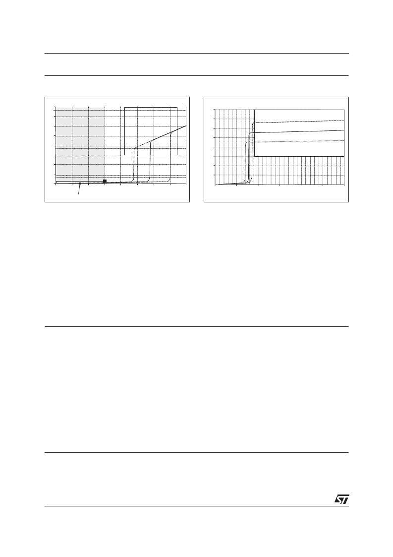
Fig. 4:
Current tranfer characteristic
0
0.5
1
1.5
2
2.5
3
3.5
4
0
5
10
15
I
20
25
30
ISOLATOR ON
I
(mA)
OUT
V (V)
Fig. 5:
Transconductance characteristic
The CLT device is used between the connector and the opto-coupler of an I/O module. To secure the
coupler off state and the non-conduction of its diode, the maximum CLT output current is 40μA with R opto
= 15k
. When the CLT input voltage V
IN
is higher than 5 V, a minimum CLT output current of 1.5 mA will
secure the opto-coupler on state.
TheCLTlimiterisinsensitivetotheoutputvoltageupto2.0V.Therefore,itsoutputisabletodriveanystate
of the art opto-coupler. Some additional device can be added in series with the opto-coupler if the output
voltage remains within its functional limits.
A stand-alone sensor is normally connected on the CLT input. For a good off state control, its quiescent
current has to be less than 1.5 mA (EN60947-5-2 standard compatible) keeping then the opto-coupler off
thanks to the CLT device (I
OUT
< 40μA). And its maximum ON state voltage V
S-ON
will be lower than 8 V
(EN60947-5-2 standard compatible) corresponding to the difference between the minimum supply voltage
(V
CC MIN
=19.2V)andthemaximumcurrentlimitationactivationvoltageV
CC MIN
=V
S-ON
+V
I
;V
I
=V
IN
+R
I
x
I
IN MAX
+ V
D
(V
I
= 11 V when V
IN
= 5 V, R
I
= 1.2 k
, I
IN
< 3.7 mA, V
D
= 1V).
APPLICATION DESCRIPTION
The input and supply pins are designed to withstand electromagnetic interferences. As shown on the
device block diagram, each channel input is protected by a clamping diode that is connected to the
common pin COM. Combined with a serial input resistance R
I
= 1.2 k
, this clamping diode implements an
effective protection against transient voltage burst (±4 kV, IEC61000-4-4) and voltage surge (±1 kV,
IEC61000-4-5).
This combination allows the surge voltage to be applied from each input to other inputs, the ground and the
supply contacts in differential or common modes (see figure 6).
Thanks to its high resistance R
C
= 4.7 k
and the conventional power supply protection that uses a
clamping diode such as the SM15T39C Transil, the supply pin V
C
withstands IEC61000-4-5 with +/-
1000 V surge voltage (see figure 7).
Finally, an external output capacitor may be placed in parallel with the opto-coupler diode to filter the
transient disturbances injected in the inputs of the module and secure the immunity of the opto-coupler
itself.
SURGE VOLTAGE TEST CIRCUIT
相關(guān)PDF資料 |
PDF描述 |
|---|---|
| CLT3-4B | CURRENT LIMITED OVER-VOLTAGE PROTECTED QUAD DIGITAL TERMINATION |
| CLT3-4BT6 | CURRENT LIMITED OVER-VOLTAGE PROTECTED QUAD DIGITAL TERMINATION |
| CM-1H8 | Miniature High Level Double Balanced Mixer 5-500 MHz |
| CM17699 | COLOR PDP DRIVER MODULE |
| CMBA847 | NPN EPITAXIAL PLANAR SILICON TRANSISTOR |
相關(guān)代理商/技術(shù)參數(shù) |
參數(shù)描述 |
|---|---|
| CLT35F-7M20 | 功能描述:非熱縮管和套管 Corr. Loom Tubing Slit, .31" (7.9mm) X 7 RoHS:否 制造商:Panduit 產(chǎn)品:Cable Wraps 類型:Spiral 顏色:Black 材料:PP 內(nèi)徑:0.03 in 長度:100 ft |
| CLT35F-C20 | 功能描述:非熱縮管和套管 Corr. Loom Tub Slit .31" (7.9mm) 100ft RoHS:否 制造商:Panduit 產(chǎn)品:Cable Wraps 類型:Spiral 顏色:Black 材料:PP 內(nèi)徑:0.03 in 長度:100 ft |
| CLT35F-C3 | 功能描述:非熱縮管和套管 Corr Loom Tubng Slit 5/16" 100’ ORNG POLY RoHS:否 制造商:Panduit 產(chǎn)品:Cable Wraps 類型:Spiral 顏色:Black 材料:PP 內(nèi)徑:0.03 in 長度:100 ft |
| CLT35F-C4 | 功能描述:非熱縮管和套管 Corr. Loom Tubing Slit, .31" (7.9mm) X 1 RoHS:否 制造商:Panduit 產(chǎn)品:Cable Wraps 類型:Spiral 顏色:Black 材料:PP 內(nèi)徑:0.03 in 長度:100 ft |
| CLT35N-7M630 | 制造商:Panduit Corp 功能描述: |
發(fā)布緊急采購,3分鐘左右您將得到回復(fù)。