- 您現(xiàn)在的位置:買賣IC網(wǎng) > PDF目錄237309 > CK1501-9PD0T 1-OUTPUT 150 W DC-DC REG PWR SUPPLY MODULE PDF資料下載
參數(shù)資料
| 型號: | CK1501-9PD0T |
| 元件分類: | 電源模塊 |
| 英文描述: | 1-OUTPUT 150 W DC-DC REG PWR SUPPLY MODULE |
| 封裝: | HEAT SINK, METAL, CASE K02, MODULE |
| 文件頁數(shù): | 15/31頁 |
| 文件大小: | 637K |
| 代理商: | CK1501-9PD0T |
第1頁第2頁第3頁第4頁第5頁第6頁第7頁第8頁第9頁第10頁第11頁第12頁第13頁第14頁當(dāng)前第15頁第16頁第17頁第18頁第19頁第20頁第21頁第22頁第23頁第24頁第25頁第26頁第27頁第28頁第29頁第30頁第31頁

Cassette Style
150 Watt DC-DC Converters
K Series
Edition 01/01.2000
22/31
Safety and Installation Instructions
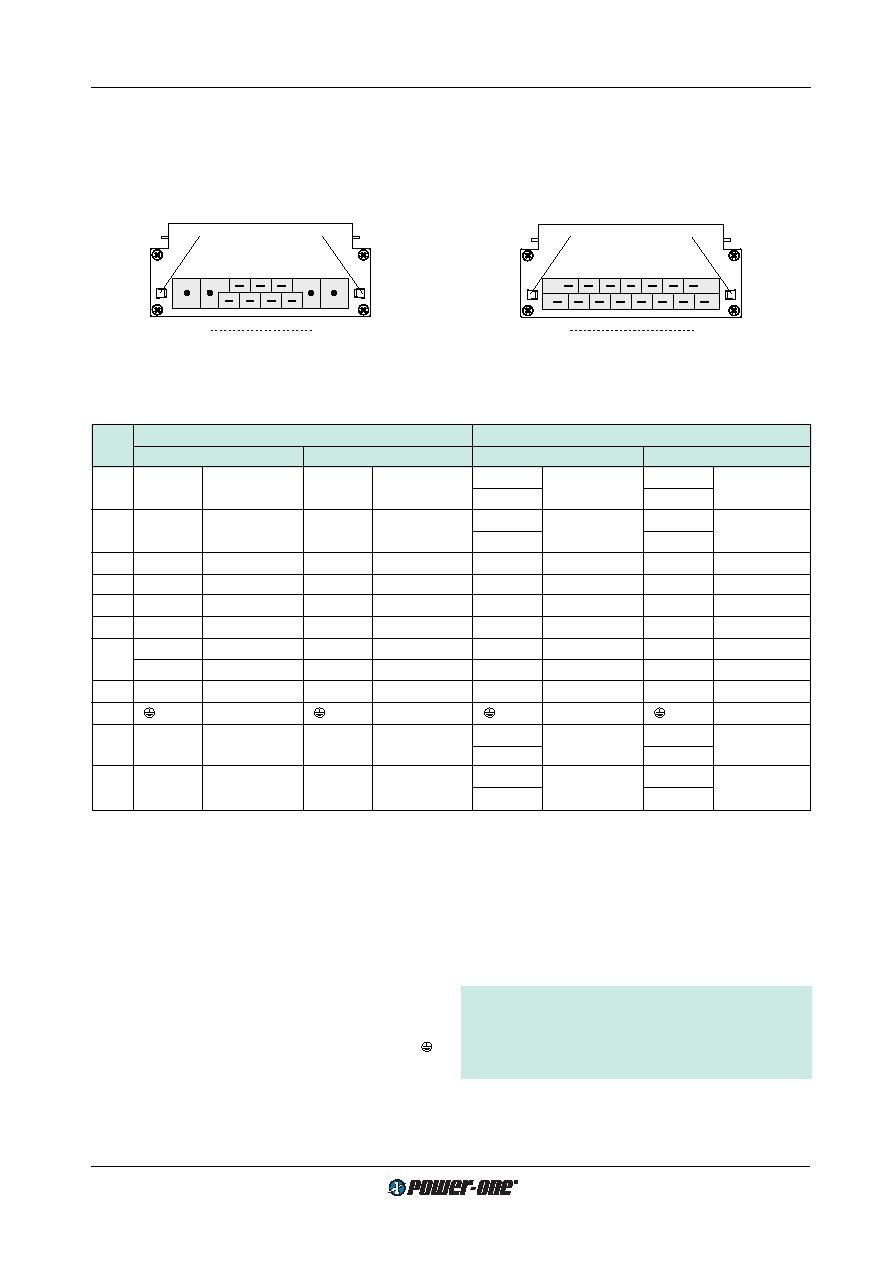
Connector Pin Allocation
The connector pin allocation table defines the electrical
potentials and the physical pin positions on the H15/H15 S4
connector. Pin no. 24, the protective earth pin present on all
Installation Instructions
The K series DC-DC converters are components, intended
exclusively for inclusion within other equipment by an in-
dustrial assembly operation or by professional installers. In-
stallation must strictly follow the national safety regulations
in compliance with the enclosure, mounting, creepage,
clearance, casualty, markings and segregation require-
ments of the end-use application.
Connection to the system shall be made via the female con-
nector H15 (see:
Accessories). Other installation methods
may not meet the safety requirements.
The DC-DC converters are provided with pin no. 24 ( ),
which is reliably connected with their case. For safety rea-
sons it is essential to connect this pin with the protective
earth of the supply system unless specified in:
Safety of op-
erator accessible output circuit.
Table 12: H15 and H15 S4 connector pin allocation
Pin
Connector type H15 S4
Connector type H 15
No.
AK 1000 (all), BK...EK 1001
AK 2000
BK…EK 1301/1501/1601
BK…EK 2000
4
Vo1+
Output 1
Vo2+
Output 2
Vo1+
Output 1
Vo2+
Output 2
6
Vo1+
Vo2+
8
Vo1–
Output 1
Vo2–
Output 2
Vo1–
Output 1
Vo2–
Output 2
10
Vo1–
Vo2–
12
S+
Sense
Vo1+
Output 1
S+
Sense
Vo1+
Output 1
14
S–
Sense
Vo1–
Output 1
S–
Sense
Vo1–
Output 1
16
R 1
Control of
U o1
R 1
Control of
U o1
R 1
Control of
U o1
R 1
Control of
U o1
18
i
Inhibit
i
Inhibit
i
Inhibit
i
Inhibit
20
D 3
Save data
D
Safe data
D
Save data
D
Save data
V 3
ACFAIL
22
T
Current sharing
T
Current sharing
T
Current sharing
T
Current sharing
24 2
Protective earth
26
Vi+
Input
Vi+
Input
Vi+
Input
Vi+
Input or Neutral
28
Vi+
30
Vi–
Input
Vi–
Input
Vi–
Input
Vi–
Input or Phase
32
Vi–
1 Feature R excludes option P and vice versa; 2 Leading pin (pregrounding); 3 Option D excludes option V and vice versa.
Fig. 23
View of module's male connectors
4/6
30/32
Type H15 S4
Fixtures for connector
retention clips V
(see Accessory Products)
10010
4
32
Type H15
Fixtures for connector
retention clips V
(see Accessory Products)
10010
An input fuse is built-in in the connection from pins no. 30
and 32 (Vi-) of the unit. Since this fuse is designed to pro-
tect the unit in case of an overcurrent and does not neces-
sarily cover all customer needs, an external fuse suitable
for the application and in compliance with the local require-
ments might be necessary in the wiring to one or both input
potentials, pins nos. 26 and 28 and/or nos. 30 and 32.
Important: Whenever the inhibit function is not in use,
pin no. 18 (i) should be connected to pin no. 14 (S–/
Vo1–) to enable the output(s).
Do not open the modules, or guarantee will be invali-
dated.
AK...FK DC-DC converters is leading, ensuring that it
makes contact with the female connector first.
相關(guān)PDF資料 |
PDF描述 |
|---|---|
| CK1501-9RD5 | 1-OUTPUT 150 W DC-DC REG PWR SUPPLY MODULE |
| CK1601-7EPD3 | 1-OUTPUT 150 W DC-DC REG PWR SUPPLY MODULE |
| CK1601-7EPD9B2 | 1-OUTPUT 150 W DC-DC REG PWR SUPPLY MODULE |
| CK1601-7ERD2 | 1-OUTPUT 150 W DC-DC REG PWR SUPPLY MODULE |
| CK1601-7PD4TB1 | 1-OUTPUT 150 W DC-DC REG PWR SUPPLY MODULE |
相關(guān)代理商/技術(shù)參數(shù) |
參數(shù)描述 |
|---|---|
| CK1507 | 制造商:Lorlin Electronics Ltd 功能描述: |
| CK1508 | 制造商:未知廠家 制造商全稱:未知廠家 功能描述:GENERAL ELECTRICAL & MECHANICAL SPECIFICATION |
| CK1509 | 制造商:未知廠家 制造商全稱:未知廠家 功能描述:GENERAL ELECTRICAL & MECHANICAL SPECIFICATION |
| CK1510 | 制造商:未知廠家 制造商全稱:未知廠家 功能描述:GENERAL ELECTRICAL & MECHANICAL SPECIFICATION |
| CK1511 | 制造商:未知廠家 制造商全稱:未知廠家 功能描述:GENERAL ELECTRICAL & MECHANICAL SPECIFICATION |
發(fā)布緊急采購,3分鐘左右您將得到回復(fù)。