- 您現(xiàn)在的位置:買賣IC網(wǎng) > PDF目錄366692 > CAT24FC32AKTE13 32K-Bit Fast Mode I2C Serial CMOS EEPROM PDF資料下載
參數(shù)資料
| 型號: | CAT24FC32AKTE13 |
| 英文描述: | 32K-Bit Fast Mode I2C Serial CMOS EEPROM |
| 中文描述: | 32K的位快速模式I2C串行CMOS EEPROM的 |
| 文件頁數(shù): | 8/12頁 |
| 文件大?。?/td> | 74K |
| 代理商: | CAT24FC32AKTE13 |

CAT24FC32A
8
Doc. No. 1048, Rev. F
Acknowledge
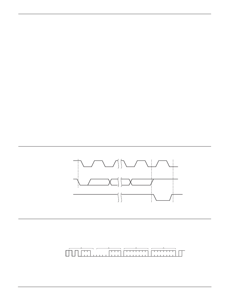
After a successful data transfer, each receiving device is
required to generate an acknowledge. The
acknowledging device pulls down the SDA line during
the ninth clock cycle, signaling that it received the 8 bits
of data. The SDA line remains stable LOW during the
HIGH period of the acknowledge related clock pulse
(Figure 8).
The CAT24FC32A responds with an acknowledge after
receiving a START condition and its slave address. If the
device has been selected along with a write operation,
it responds with an acknowledge after receiving each 8-
bit byte. The CAT24FC32A does not generate
acknowledge if an internal write cycle is in progress.
When the CAT24FC32A begins a READ mode it transmits
8 bits of data, releases the SDA line, and monitors the
line for an acknowledge. Once it receives this
acknowledge, the CAT24FC32A will continue to transmit
data. If no acknowledge is sent by the Master, the device
terminates data transmission and waits for a STOP
condition. The master must then issue a stop condition
to return the CAT24FC32A to the standby power mode
and place the device in a known state.
Figure 8. Acknowledge Timing
WRITE OPERATIONS
Byte Write
In the Byte Write mode, the Master device sends the
START condition and the slave address information
(with the R/
W
bit set to zero) to the Slave device. After
the Slave generates an acknowledge, the Master sends
two 8-bit address words that are to be written into the
address pointers of the CAT24FC32A. After receiving
another acknowledge from the Slave, the Master device
transmits the data to be written into the addressed
memory location. The CAT24FC32A acknowledges once
more and the Master generates the STOP condition. At
this time, the device begins an internal programming
cycle to nonvolatile memory. While the cycle is in
progress, the device will not respond to any request from
the Master device.
Page Write
The CAT24FC32A writes up to 32 bytes of data, in a
single write cycle, using the Page Write operation. The
page write operation is initiated in the same manner as
the byte write operation, however instead of terminating
after the initial byte is transmitted, the Master is allowed
to send up to 31 additional bytes. After each byte has
ACKNOWLEDGE
1
START
SCL FROM
MASTER
8
9
DATA OUTPUT
FROM TRANSMITTER
DATA OUTPUT
FROM RECEIVER
Figure 9. Byte Write Timing
A15—A 8
SLAVE
ADDRESS
S
A
C
K
A
C
K
DATA
A
C
K
S
T
O
P
P
BUS ACTIVITY:
MASTER
SDA LINE
S
T
A
R
T
A7—A 0
BYTE ADDRESS
A
C
K
X
X
X X
X = Don't care bit
相關PDF資料 |
PDF描述 |
|---|---|
| CAT24FC32A | LM5102 High Voltage Half-Bridge Gate Driver with Programmable Delay; Package: LLP; No of Pins: 10 |
| CAT24FC32ALTE13 | LM5102 High Voltage Half-Bridge Gate Driver with Programmable Delay; Package: LLP; No of Pins: 10 |
| CAT24FC32AXTE13 | LM5104 High Voltage Half-Bridge Gate Driver with Adaptive Delay; Package: SOIC NARROW; No of Pins: 8 |
| CAT24FC32AYTE13 | ER 2C 2#8 SKT PLUG |
| CAT24FC32AWTE13 | 32K-Bit Fast Mode I2C Serial CMOS EEPROM |
相關代理商/技術參數(shù) |
參數(shù)描述 |
|---|---|
| CAT24FC64LI | 制造商:Rochester Electronics LLC 功能描述: 制造商:Catalyst Semiconductor 功能描述: |
| CAT24FC64WI-TE13 | 制造商:Catalyst Semiconductor 功能描述: |
| CAT24FC64YI | 制造商:Rochester Electronics LLC 功能描述: 制造商:Catalyst Semiconductor 功能描述: |
| CAT24FC64YI-TE13 | 制造商:Rochester Electronics LLC 功能描述: 制造商:Catalyst Semiconductor 功能描述: |
| CAT24G | 制造商:Semiconductors 功能描述: |
發(fā)布緊急采購,3分鐘左右您將得到回復。