- 您現(xiàn)在的位置:買(mǎi)賣(mài)IC網(wǎng) > PDF目錄378756 > CA3108A36-8P (ITT Corporation) Circular Connectors PDF資料下載
參數(shù)資料
| 型號(hào): | CA3108A36-8P |
| 廠(chǎng)商: | ITT Corporation |
| 元件分類(lèi): | 圓形連接器 |
| 英文描述: | Circular Connectors |
| 中文描述: | 圓形連接器 |
| 文件頁(yè)數(shù): | 4/5頁(yè) |
| 文件大?。?/td> | 2024K |
| 代理商: | CA3108A36-8P |
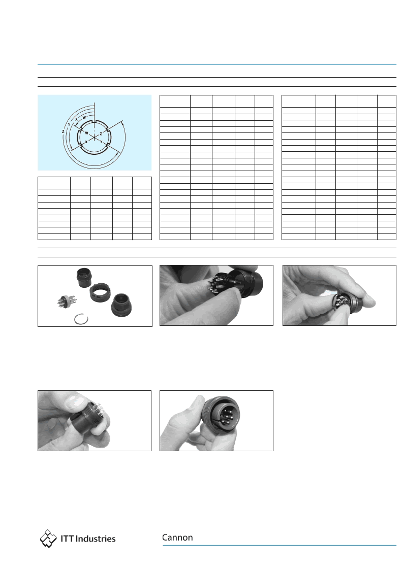
Pin front view: Shell rotation
Contact
Arrangement
14S-9
16-9
16-10
16-11
16S-1
16S-8
18-1
18-4
18-5
18-8
18-9
18-10
18-11
18-12
18-20
18-22
20-3
20-4
20-7
20-19
20-27
W
70
35
90
35
80
—
70
35
80
70
80
—
—
80
90
70
70
45
80
90
35
X
145
110
180
110
—
170
145
110
110
—
110
120
170
—
180
145
145
110
110
180
110
Y
215
250
270
250
—
265
215
250
250
—
250
240
265
—
270
215
215
250
250
270
250
Z
290
325
—
325
280
—
290
325
280
290
280
—
—
280
—
290
290
—
280
—
325
Contact
Arrangement
20-29
20-33
22-2
22-14
22-19
22-23
22-28
24-2
24-10
24-20
24-28
28-10
28-11
28-12
28-15
28-16
28-21
36-5
36-7
36-8
36-10
W
80
35
70
80
80
35
80
80
80
80
80
80
80
90
80
80
80
—
80
80
80
X
—
110
145
—
110
—
—
—
—
110
110
110
110
180
110
110
110
120
110
110
125
Y
—
256
215
—
250
250
—
—
—
250
250
250
250
270
250
250
250
240
250
250
235
Z
280
325
290
280
280
—
280
280
280
280
280
280
280
—
280
280
280
—
280
280
280
Dimensions are shown in mm (inch)
Dimensions subject to change
www.ittcannon.com
Circular
CA/MS A&B
Assembly Instructions
Step 3: Confirm insulator is fixed inside shell by
applying slight force on the engaging side of
the insulator. If properly installed, the insulator
can not be pushed out the rear of the shell. If
the insulator is displaced with this test, please
repeat steps 1 and 2.
Step 4: Complete assembly by adding coupling
nut and endbell. Please note that the coupling
nut is used on the plug side only.
*Note:During installation, ensure that all contacts remain fixed. If
during this process the contacts rotate out of position, separate
the 2 piece insulator and adjust accordingly.
Alternate Insert Positions
Step 2: After insulator is seated in shell, install
the snap ring on the rear of the connector.
Slightly compress ring and insert into recessed
area just above the insulator. If not completely
in place, manipulate the snap ring with finger
until visual or audible seating confirmation is
made. No tooling is required.
Step 1*: Remove tape from insulator. With the
insulator and shell positioned as shown above,
polarize insulator to desired position and place
inside shell using the internal keyway as
guide. Once inside the shell, the insulator
cannot rotate. However, until the snap ring is
applied in step 2, the insulator is not
captivated in the shell.
Unassembled connectors are supplied in kits,
an insulator kit and hardware kit. The insulator
kit includes a snap ring and insulator with
preloaded contacts. The hardware kit includes
the shell along with appropriate endbell
(except box mount receptacles) and coupling
nut (plug only).
Contact
Arrangement
10SL-3
10SL-4
12S-3
14S-1
14S-2
14S-5
14S-6
14S-7
W
—
—
70
—
—
—
—
90
X
—
—
145
—
120
110
—
180
Y
—
—
215
—
240
—
—
270
Z
—
—
290
—
—
—
—
—
4
相關(guān)PDF資料 |
PDF描述 |
|---|---|
| CA3108A36-8S | Circular Connectors |
| CA3108B10SL-8P | Circular Connectors |
| CA3108B10SL-8S | Circular Connectors |
| CA3108B12S-8P | Circular Connectors |
| CA3108B12S-8S | Circular Connectors |
相關(guān)代理商/技術(shù)參數(shù) |
參數(shù)描述 |
|---|---|
| CA3108A36-8S | 制造商:ITT 制造商全稱(chēng):ITT Industries 功能描述:Circular Connectors |
| CA3108B10SL-3SA206 | 功能描述:AB 3C 3#16S SKT PLUG 制造商:itt cannon, llc 系列:* 零件狀態(tài):有效 標(biāo)準(zhǔn)包裝:1 |
| CA3108B10SL-8P | 制造商:ITT 制造商全稱(chēng):ITT Industries 功能描述:Circular Connectors |
| CA3108B10SL-8S | 制造商:ITT 制造商全稱(chēng):ITT Industries 功能描述:Circular Connectors |
| CA3108B12S-3S | 制造商:ITT Interconnect Solutions 功能描述:CONN 5015 CIRC SKT 2 POS SLDR RA CBL MNT - Bulk |
發(fā)布緊急采購(gòu),3分鐘左右您將得到回復(fù)。