- 您現(xiàn)在的位置:買賣IC網 > PDF目錄369552 > BU3883 (78.61 k) PDF資料下載
參數(shù)資料
| 型號: | BU3883 |
| 英文描述: | (78.61 k) |
| 中文描述: | (78.61十一) |
| 文件頁數(shù): | 3/7頁 |
| 文件大小: | 78K |
| 代理商: | BU3883 |

3
Video ICs
BU38603 / BU38703 / BU38803
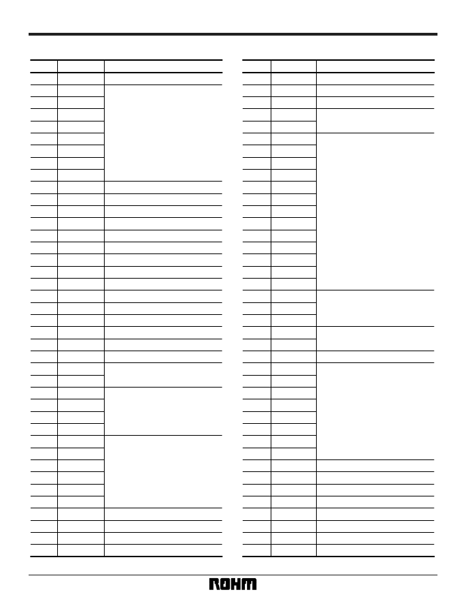
Pin descriptions
Pin No.
1
VSAD
2
ADC0
3
ADC1
4
ADC2
5
ADC3
6
ADC4
7
ADC5
8
ADC6
9
ADC7
10
VDAD
11
DFGOUT
12
DFGIN
13
DPGIN
14
CFGIN
15
CFGOUT
16
VSSA
17
V
ref
18
CTLAMP –
19
CTLAMPOUT
20
CTL –
21
CTL +
22
VDDA
23
RESETB
24
TEST
25
PO5
26
PO4
27
P31
28
P30
29
P29
30
P28
31
P27
32
P26
33
P25
34
P24
35
P23
36
P22
37
PO3
38
VHSW
39
AHSW
40
HAMPSW
41
CHROT
42
FV
43
V
DD
44
PWM0
45
PWM1
46
P21
47
P20
48
P19
49
P18
50
P17
51
P16
52
P15
53
P14
54
P13
55
P12
56
P11
57
P10
58
59
PO2
60
PO1
61
PO0
62
CLOCKO
63
CLOCKI
64
V
SS
65
P8
66
P7
67
P6
68
P5
69
P4
70
P3
71
P2
72
P1
73
P0
74
SI
75
SO
76
SCK
77
ENVIN
78
CSYNC
79
COUNTP
80
PBCTL
P9
Pin name
Function
Pin name
Pin No.
Function
A / D convertor circuit GND.
Can be optionally mask – programmed
to be either A / D or parallel inputs.
A / D convertor circuit power supply.
Drum FG amplifier output
Drum FG amplifier input
Drum PG comparator input
Capstan FG amplifier input
Capstan FG amplifier output
Linear circuit GND
Internal BIAS and power-on reset pin
CTL amplifier – input
CTL amplifier output
CTL coil – connection
CTL coil + connection
Linear circuit power supply
Power supply reset
Test mode input (normally GND)
Parallel output
Parallel I / O
Parallel I / O and pattern generator
output
Pattern generator VHSW output
Chroma rotary switch output
Pseudo Vsync output
Logic circuit power supply
PWM output
Parallel I / O
Parallel output
For connection of oscillator
Logic circuit GND
Parallel I / O
Parallel I / O and external interrupt
Serial I / O data input
Serial I / O data I / O
Serial I / O clock I / O
Envelope detector logic input
Composite signal logic input
CTL counter pulse output
CTL logic output
Parallel output and pattern generator output
Head amplifier switch output
Pattern generator AHSW output
相關PDF資料 |
PDF描述 |
|---|---|
| BU3892FV | CD-Player Support Circuit |
| BU38905 | Capstan/Servo Circuit For VCR |
| BU4016B | SPST Analog Switch |
| BU4051BF | 8-Channel Analog Multiplexer |
| BU4052B | 4-Channel Analog Multiplexer |
相關代理商/技術參數(shù) |
參數(shù)描述 |
|---|---|
| BU38905 | 制造商:未知廠家 制造商全稱:未知廠家 功能描述:Capstan/Servo Circuit For VCR |
| BU3892FV | 制造商:未知廠家 制造商全稱:未知廠家 功能描述:CD-Player Support Circuit |
| BU38UA3WNVX-TL | 制造商:ROHM 制造商全稱:Rohm 功能描述:Versatile Package FULL CMOS LDO Regulator |
| BU39UA3WNVX-TL | 制造商:ROHM 制造商全稱:Rohm 功能描述:Versatile Package FULL CMOS LDO Regulator |
| BU3AUA3WNVX-TL | 制造商:ROHM 制造商全稱:Rohm 功能描述:Versatile Package FULL CMOS LDO Regulator |
發(fā)布緊急采購,3分鐘左右您將得到回復。