- 您現(xiàn)在的位置:買賣IC網(wǎng) > PDF目錄256397 > BU-61843F3-880 (DATA DEVICE CORP) 2 CHANNEL(S), 1M bps, MIL-STD-1553 CONTROLLER, CQFP72 PDF資料下載
參數(shù)資料
| 型號: | BU-61843F3-880 |
| 廠商: | DATA DEVICE CORP |
| 元件分類: | 微控制器/微處理器 |
| 英文描述: | 2 CHANNEL(S), 1M bps, MIL-STD-1553 CONTROLLER, CQFP72 |
| 封裝: | 1 X 1 INCH, 0.155 INCH HEIGHT, CERAMIC, FP-72 |
| 文件頁數(shù): | 13/60頁 |
| 文件大?。?/td> | 700K |
| 代理商: | BU-61843F3-880 |
第1頁第2頁第3頁第4頁第5頁第6頁第7頁第8頁第9頁第10頁第11頁第12頁當(dāng)前第13頁第14頁第15頁第16頁第17頁第18頁第19頁第20頁第21頁第22頁第23頁第24頁第25頁第26頁第27頁第28頁第29頁第30頁第31頁第32頁第33頁第34頁第35頁第36頁第37頁第38頁第39頁第40頁第41頁第42頁第43頁第44頁第45頁第46頁第47頁第48頁第49頁第50頁第51頁第52頁第53頁第54頁第55頁第56頁第57頁第58頁第59頁第60頁
20
Data Device Corporation
www.ddc-web.com
BU-6174X/6184X/6186X
Rev. C
8
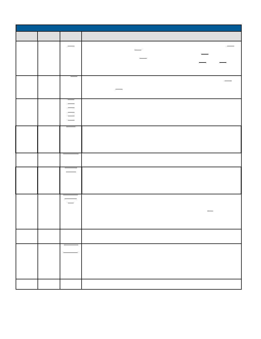
TABLE 37. BC CONDITION CODES
BIT
CODE
LT/GP0
EQ/GP1
RETRY0
RETRY1
RETRY0
RETRY01
D
E
GP2
GP3
GP4
GP5
GP6
GP7
NORESP
GD BLK
XFER
NAME
(BIT 4 = 0)
These two bits reflect the retry status of the most recent message. The number of times that the mes-
sage was retried is delineated by these two bits as shown below:
RETRY COUNT 1
RETRY COUNT 0
Number of
(bit 14)
(bit 13)
Message Retries
0
1
0
N/A
1
2
FUNCTIONAL DESCRIPTION
INVERSE
(BIT 4 = 1)
GT-EQ/
GP0
NE/GP1
0
ALWAYS
Less than or GP0 flag. This bit is set or cleared based on the results of the compare. If the value of the
CMT's parameter is less than the value of the message time counter, then the LT/GP0 and NE/GP1
flags will be set, while the GT-EQ/GP0 and EQ/GP1 flags will be cleared. If the value of the CMT's
parameter is equal to the value of the message time counter, then the GT-EQ/GP0 and EQ/GP1 flags
will be set, while the LT/GP0 and NE/GP1 flags will be cleared. If the value of the CMT's parameter is
greater than the current value of the message time counter, then the GT-EQ/GP0 and NE/GP1 flags will
be set , while the LT/GP0 and EQ/GP1 flags will be cleared. Also, General Purpose Flag 1 may be also
be set or cleared by a FLG operation.
NEVER
F
GP2
GP3
GP4
GP5
GP6
GP7
1
RESP
Equal Flag. This bit is set or cleared after CFT or CMT operation. If the value of the CMT's parameter is
equal to the value of the message time counter, then the EQ/GP1 flag will be set and the NE/GP1 bit
will be cleared. If the value of the CMT's parameter is not equal to the value of the message time
counter, then the NE/GP1 flag will be set and the EQ/GP1bit will be cleared. Also, General Purpose
Flag 1 may be also be set or cleared by a FLG operation.
GD BLK
XFER
BAD
MESSAGE
GOOD
MESSAGE
The ALWAYS bit should be set to designate an instruction as unconditional. The inverse (NEVER) bit
can be used to implement a NOP instruction.
C
BAD MESSAGE indicates either a format error, loop test fail, or no response error for the most recent
message. Note that a "Status Set" condition has no effect on the "BAD MESSAGE/GOOD MESSAGE"
condition code.
FMT ERR
9
FMT ERR indicates that the received portion of the most recent message contained one or more viola-
tions of the 1553 message validation criteria (sync, encoding, parity, bit count, word count, etc.), or the
RT's status word received from a responding RT contained an incorrect RT address field.
MASKED
STATUS
BIT
MASKED
STATUS
BIT
B
General Purpose Flags may be set, cleared, or toggled by a FLG operation. The host processor can
set, clear, or toggle these flags in the same way as the FLG instruction by means of the BC GENERAL
PURPOSE FLAG REGISTER.
Indicates that one or both of the following conditions have occurred for the most recent message: (1) If
one (or more) of the Status Mask bits (14 through 9) in the BC Control Word is logic "0" and the corre-
sponding bit(s) is (are) set (logic "1") in the received RT Status Word. In the case of the RESERVED
BITS MASK (bit 9) set to logic "0," any or all of the 3 Reserved Status Word bits being set will result in
a MASKED STATUS SET condition; and/or (2) If BROADCAST MASK ENABLED/XOR (bit 11 of
Configuration Register #4) is logic "1" and the MASK BROADCAST bit of the message's BC Control
Word is logic "0" and the BROADCAST COMMAND RECEIVED bit in the received RT Status Word is
logic "1.".
2
3
4
5
6
7
NORESP indicates that an RT has either not responded or has responded later than the BC No
Response Timeout time. The Enhanced Mini-ACE's No Response Timeout Time is defined per
MIL-STD-1553B as the time from the mid-bit crossing of the parity bit of the last word transmitted by
the BC to the mid-sync crossing of the RT Status Word. The value of the No Response Timeout value
is programmable from among the nominal values 18.5, 22.5, 50.5, and 130 s (±1 s) by means of bits
10 and 9 of Configuration Register #5.
A
For the most recent message, GD BLK XFER will be set to logic "1" following completion of a valid
(error-free) RT-to-BC transfer, RT-to-RT transfer, or transmit mode code with data message. This bit is
set to logic "0" following an invalid message. GOOD DATA BLOCK TRANSFER is always logic "0" fol-
lowing a BC-to-RT transfer, a mode code with data, or a mode code without data. The Loop Test has
no effect on GOOD DATA BLOCK TRANSFER. GOOD DATA BLOCK TRANSFER may be used to
determine if the transmitting portion of an RT-to-RT transfer was error free.
相關(guān)PDF資料 |
PDF描述 |
|---|---|
| BU-61843F4-260Y | 2 CHANNEL(S), 1M bps, MIL-STD-1553 CONTROLLER, CQFP72 |
| BU-61843F4-360Z | 2 CHANNEL(S), 1M bps, MIL-STD-1553 CONTROLLER, CQFP72 |
| BU-61843F4-520 | 2 CHANNEL(S), 1M bps, MIL-STD-1553 CONTROLLER, CQFP72 |
| BU-61843F4-740W | 2 CHANNEL(S), 1M bps, MIL-STD-1553 CONTROLLER, CQFP72 |
| BU-61843G3-100Y | 2 CHANNEL(S), 1M bps, MIL-STD-1553 CONTROLLER, CQFP72 |
相關(guān)代理商/技術(shù)參數(shù) |
參數(shù)描述 |
|---|---|
| BU-61843F4-100 | 制造商:未知廠家 制造商全稱:未知廠家 功能描述:Telecommunication IC |
| BU-61843F4-110 | 制造商:未知廠家 制造商全稱:未知廠家 功能描述:Telecommunication IC |
| BU-61843G3-100 | 制造商:未知廠家 制造商全稱:未知廠家 功能描述:Telecommunication IC |
| BU-61843G3-110 | 制造商:未知廠家 制造商全稱:未知廠家 功能描述:Telecommunication IC |
| BU-61843G4-100 | 制造商:未知廠家 制造商全稱:未知廠家 功能描述:Telecommunication IC |
發(fā)布緊急采購,3分鐘左右您將得到回復(fù)。