- 您現(xiàn)在的位置:買賣IC網(wǎng) > PDF目錄166586 > BU-61745F3-802S (DATA DEVICE CORP) 2 CHANNEL(S), 1M bps, MIL-STD-1553 CONTROLLER, CQFP72 PDF資料下載
參數(shù)資料
| 型號: | BU-61745F3-802S |
| 廠商: | DATA DEVICE CORP |
| 元件分類: | 微控制器/微處理器 |
| 英文描述: | 2 CHANNEL(S), 1M bps, MIL-STD-1553 CONTROLLER, CQFP72 |
| 封裝: | 25.40 X 25.40 MM, 3.94 MM HEIGHT, CERAMIC, FP-72 |
| 文件頁數(shù): | 37/60頁 |
| 文件大小: | 457K |
| 代理商: | BU-61745F3-802S |
第1頁第2頁第3頁第4頁第5頁第6頁第7頁第8頁第9頁第10頁第11頁第12頁第13頁第14頁第15頁第16頁第17頁第18頁第19頁第20頁第21頁第22頁第23頁第24頁第25頁第26頁第27頁第28頁第29頁第30頁第31頁第32頁第33頁第34頁第35頁第36頁當(dāng)前第37頁第38頁第39頁第40頁第41頁第42頁第43頁第44頁第45頁第46頁第47頁第48頁第49頁第50頁第51頁第52頁第53頁第54頁第55頁第56頁第57頁第58頁第59頁第60頁

42
Data Device Corporation
www.ddc-web.com
BU-6174X/6184X/6186X
F-10/02-300
THERMAL AND MECHANICAL MANAGEMENT FOR
-ACE (BGA PACKAGE)
Ball Grid Array (BGA) components necessitate that thermal
management issues be considered early in the design stage for
MIL-STD-1553 terminals. This is especially true if high transmit-
ter duty cycles are expected. The temperature range specified for
DDC's -ACE device refers to the temperature at the ball, not the
case.
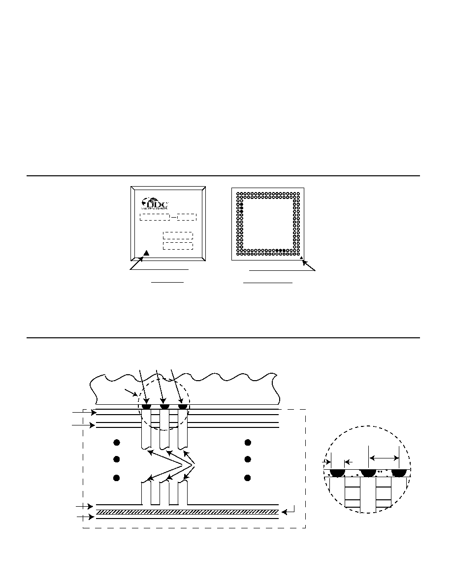
All -ACE devices incorporate six package connections (E2, F2,
G2, U13, U14, and U15), which perform the dual function of cir-
cuit ground and thermal heat sink. Refer to FIGURE 16 for con-
nection locations. It is mandatory that these six balls be con-
Thermal Balls
(Two groups: E2, F2, G2;
and U13, U14, U15)
PC Board
-ACE
(BGA Package)
Thermal Plane
Signal Ground
Plane
Thermal Vias
Prepreg,
Approx. 0.003" thick
Top (component)
Layer
Signal Layer
0.022"
dia.
0.0394"
Pitch
Detail A
nected to a circuit ground plane (a circuit trace is insufficient)
through thermal vias as shown in FIGURE 17. Operation without
an adequate ground/thermal plane is not recommended and
extended exposure to these conditions may affect device relia-
bility.
The purpose of this ground/thermal plane is to conduct the heat
being generated by the transceivers within the package and con-
duct this heat away from the -ACE. In general, the circuit ground
and thermal (chassis) ground are not the same ground plane. It
is acceptable for these six balls to be directly soldered to a
ground plane but it must be located in close physical and thermal
proximity ("0.003" pre-preg layer recommended) to the thermal
plane (See FIGURE 17).
FIGURE 17. THERMAL DESIGN FOR -ACE (BGA PACKAGES)
FIGURE 16. THERMAL BALL LOCATIONS FOR -ACE (BGA PACKAGES)
V U T R P N M L K J H G F E D C B A
18
17
16
15
14
13
12
11
10
9
8
7
6
5
4
3
2
1
BOTTOM VIEW
Notes:
1) E2, F2, G2, U13, U14 and U15 must be connected
to a thermal plane to maintain recommended operating temperature.
(USA)
S/N
D/C
TOP VIEW
ESD and Pin 1 Identifier
相關(guān)PDF資料 |
PDF描述 |
|---|---|
| BU-61745G3-100L | 2 CHANNEL(S), 1M bps, MIL-STD-1553 CONTROLLER, CQFP72 |
| BU-61745G3-200L | 2 CHANNEL(S), 1M bps, MIL-STD-1553 CONTROLLER, CQFP72 |
| BU-61745G3-400W | 2 CHANNEL(S), 1M bps, MIL-STD-1553 CONTROLLER, CQFP72 |
| BU-61745G3-420Q | 2 CHANNEL(S), 1M bps, MIL-STD-1553 CONTROLLER, CQFP72 |
| BU-61745G3-470Q | 2 CHANNEL(S), 1M bps, MIL-STD-1553 CONTROLLER, CQFP72 |
相關(guān)代理商/技術(shù)參數(shù) |
參數(shù)描述 |
|---|---|
| BU-61745F4-100 | 制造商:未知廠家 制造商全稱:未知廠家 功能描述:Telecommunication IC |
| BU-61745F4-110 | 制造商:未知廠家 制造商全稱:未知廠家 功能描述:Telecommunication IC |
| BU-61745G3-100 | 制造商:未知廠家 制造商全稱:未知廠家 功能描述:Telecommunication IC |
| BU-61745G3-110 | 制造商:未知廠家 制造商全稱:未知廠家 功能描述:Telecommunication IC |
| BU-61745G4-100 | 制造商:未知廠家 制造商全稱:未知廠家 功能描述:Telecommunication IC |
發(fā)布緊急采購,3分鐘左右您將得到回復(fù)。