- 您現(xiàn)在的位置:買賣IC網(wǎng) > PDF目錄256198 > BU-61705G3-392K (DATA DEVICE CORP) 2 CHANNEL(S), 1M bps, MIL-STD-1553 CONTROLLER, CQFP72 PDF資料下載
參數(shù)資料
| 型號: | BU-61705G3-392K |
| 廠商: | DATA DEVICE CORP |
| 元件分類: | 微控制器/微處理器 |
| 英文描述: | 2 CHANNEL(S), 1M bps, MIL-STD-1553 CONTROLLER, CQFP72 |
| 封裝: | CERAMIC, QFP-72 |
| 文件頁數(shù): | 34/54頁 |
| 文件大小: | 576K |
| 代理商: | BU-61705G3-392K |
第1頁第2頁第3頁第4頁第5頁第6頁第7頁第8頁第9頁第10頁第11頁第12頁第13頁第14頁第15頁第16頁第17頁第18頁第19頁第20頁第21頁第22頁第23頁第24頁第25頁第26頁第27頁第28頁第29頁第30頁第31頁第32頁第33頁當前第34頁第35頁第36頁第37頁第38頁第39頁第40頁第41頁第42頁第43頁第44頁第45頁第46頁第47頁第48頁第49頁第50頁第51頁第52頁第53頁第54頁
4
Data Device Corporation
www.ddc-web.com
BU-61703/61705
D1 web-09/02-0
oz
(g)
in.
(mm)
°C
°C/W
°C
+125
+85
+70
11
125
160
150
+300
9
-55
-40
0
-55
-65
Weight
Flatpack/Gull lead package
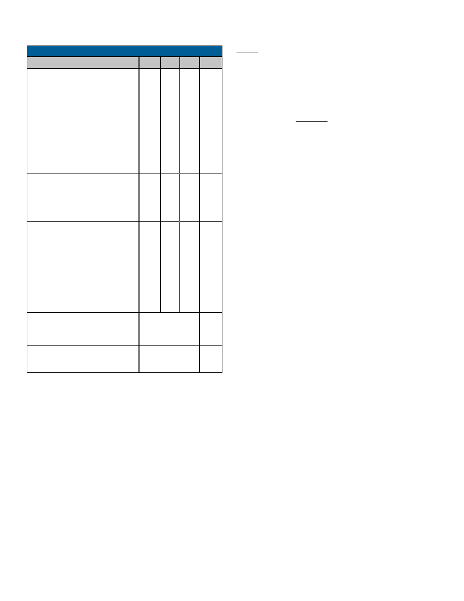
PHYSICAL CHARACTERISTICS
Size
Ceramic Flatpack / Gull Lead
THERMAL
-1XX, -4XX
-2XX, -5XX
-3XX, -8XX
Ceramic Flatpack / Gull Lead
Thermal Resistance, Junction-to-
Case, Hottest Die (
θJC)
Max Case Temperature
Operating Junction Temperature
Storage Temperature
Lead Temperature (soldering, 10
sec.)
s
19.5
7
18.5
660.5
17.5
4
1553 MESSAGE TIMING
RT-to-RT Response Timeout
(Note 12)
RT Response Time
(mid-parity to mid-sync) (Note 12)
Transmitter Watchdog Timeout
MHz
%
0.01
0.10
0.001
0.01
60
16.0
12.0
10.0
20.0
-0.01
-0.10
-0.001
-0.01
40
CLOCK INPUT
Frequency
Nominal Value
Default
Option
Long Term Tolerance
1553A Compliance
1553B Compliance
Short Term Tolerance, 1 second
1553A Compliance
1553B Compliance
Duty Cycle
UNITS
MAX
TYP
MIN
PARAMETER
TABLE 1. SIMPLE SYSTEM RT SPECS. (Cont’d)
0.6
(17)
1.0 X 1.0 X 0.155
(25.4 x 25.4 x 3.94)
NOTES:
Notes 1 through 6 are applicable to the Receiver Differential Resistance
and Differential Capacitance specifications:
(1)
Specifications include both transmitter and receiver (tied together
internally).
(2)
Impedance parameters are specified directly between pins
TX/RX A(B) and TX/RX A(B) of the SSRT hybrid.
(3)
It is assumed that all power and ground inputs to the hybrid are con-
nected.
(4)
The specifications are applicable for both unpowered and powered
conditions.
(5)
The specifications assume a 2 volt rms balanced, differential, sinu-
soidal input. The applicable frequency range is 75 kHz to 1 MHz.
(6)
Minimum resistance and maximum capacitance parameters are
guaranteed over the operating range, but are not tested.
(7)
Assumes a common mode voltage within the frequency range of dc
to 2 MHz, applied to the pins of the isolation transformer on the stub
side (either direct or transformer coupled), and referenced to hybrid
ground. Transformer must be a DDC recommended transformer or
other transformer that provides an equivalent minimum CMRR.
(8)
An "X" in one or more of the product type fields indicates that the ref-
erence is applicable to all available product options.
(9)
MIL-STD-1760 requires an output of 20 Vp-p minimum on the stub
connection.
(10) External 10 F tantalum and 0.1 F capacitors to ground should be
located as close as possible to Pins 20 and 72, and a 0.1 F capac-
itor at pin 37.
(11) Power dissipation specifications assume a transformer coupled con-
figuration, with external dissipation (while transmitting) of 0.14 watts
for the active isolation transformer, 0.08 watts for the active bus cou-
pling transformer, 0.45 watts for each of the two bus isolation resis-
tors, and 0.15 watts for each of the two bus termination resistors.
(12) Measured from mid-parity crossing of command word to mid-sync
crossing of RT's status word.
(13) MIL-STD-1760
compliant
output
voltage
not
available
for
BU-61703/5X4 versions.
相關(guān)PDF資料 |
PDF描述 |
|---|---|
| BU-61705G3-892Q | 2 CHANNEL(S), 1M bps, MIL-STD-1553 CONTROLLER, CQFP72 |
| BU-61705G4-200L | 2 CHANNEL(S), 1M bps, MIL-STD-1553 CONTROLLER, CQFP72 |
| BU-61705G4-410W | 2 CHANNEL(S), 1M bps, MIL-STD-1553 CONTROLLER, CQFP72 |
| BU-61705G4-420Z | 2 CHANNEL(S), 1M bps, MIL-STD-1553 CONTROLLER, CQFP72 |
| BU-61705G4-490Y | 2 CHANNEL(S), 1M bps, MIL-STD-1553 CONTROLLER, CQFP72 |
相關(guān)代理商/技術(shù)參數(shù) |
參數(shù)描述 |
|---|---|
| BU-61740B3NEW | 制造商:未知廠家 制造商全稱:未知廠家 功能描述:MIL-STD-1553 Components |μ-ACE (Micro-ACE?) |
| BU-61743 | 制造商:未知廠家 制造商全稱:未知廠家 功能描述:MIL-STD-1553 Components |Enhanced Mini-ACE? |
| BU-61743F3-100 | 制造商:未知廠家 制造商全稱:未知廠家 功能描述:Telecommunication IC |
| BU-61743F3-110 | 制造商:未知廠家 制造商全稱:未知廠家 功能描述:Telecommunication IC |
| BU-61743F4-100 | 制造商:未知廠家 制造商全稱:未知廠家 功能描述:Telecommunication IC |
發(fā)布緊急采購,3分鐘左右您將得到回復(fù)。