- 您現在的位置:買賣IC網 > PDF目錄369507 > BT136F-600D Electrical Outlet Connector; Leaded Process Compatible:Yes; RoHS Compliant:Yes PDF資料下載
參數資料
| 型號: | BT136F-600D |
| 英文描述: | Electrical Outlet Connector; Leaded Process Compatible:Yes; RoHS Compliant:Yes |
| 中文描述: | 晶閘管產品目錄 |
| 文件頁數: | 90/224頁 |
| 文件大小: | 2697K |
| 代理商: | BT136F-600D |
第1頁第2頁第3頁第4頁第5頁第6頁第7頁第8頁第9頁第10頁第11頁第12頁第13頁第14頁第15頁第16頁第17頁第18頁第19頁第20頁第21頁第22頁第23頁第24頁第25頁第26頁第27頁第28頁第29頁第30頁第31頁第32頁第33頁第34頁第35頁第36頁第37頁第38頁第39頁第40頁第41頁第42頁第43頁第44頁第45頁第46頁第47頁第48頁第49頁第50頁第51頁第52頁第53頁第54頁第55頁第56頁第57頁第58頁第59頁第60頁第61頁第62頁第63頁第64頁第65頁第66頁第67頁第68頁第69頁第70頁第71頁第72頁第73頁第74頁第75頁第76頁第77頁第78頁第79頁第80頁第81頁第82頁第83頁第84頁第85頁第86頁第87頁第88頁第89頁當前第90頁第91頁第92頁第93頁第94頁第95頁第96頁第97頁第98頁第99頁第100頁第101頁第102頁第103頁第104頁第105頁第106頁第107頁第108頁第109頁第110頁第111頁第112頁第113頁第114頁第115頁第116頁第117頁第118頁第119頁第120頁第121頁第122頁第123頁第124頁第125頁第126頁第127頁第128頁第129頁第130頁第131頁第132頁第133頁第134頁第135頁第136頁第137頁第138頁第139頁第140頁第141頁第142頁第143頁第144頁第145頁第146頁第147頁第148頁第149頁第150頁第151頁第152頁第153頁第154頁第155頁第156頁第157頁第158頁第159頁第160頁第161頁第162頁第163頁第164頁第165頁第166頁第167頁第168頁第169頁第170頁第171頁第172頁第173頁第174頁第175頁第176頁第177頁第178頁第179頁第180頁第181頁第182頁第183頁第184頁第185頁第186頁第187頁第188頁第189頁第190頁第191頁第192頁第193頁第194頁第195頁第196頁第197頁第198頁第199頁第200頁第201頁第202頁第203頁第204頁第205頁第206頁第207頁第208頁第209頁第210頁第211頁第212頁第213頁第214頁第215頁第216頁第217頁第218頁第219頁第220頁第221頁第222頁第223頁第224頁

http://www.teccor.com
+1 972-580-7777
E9 - 4
2002 Teccor Electronics
Thyristor Product Catalog
Sidac
Data Sheets
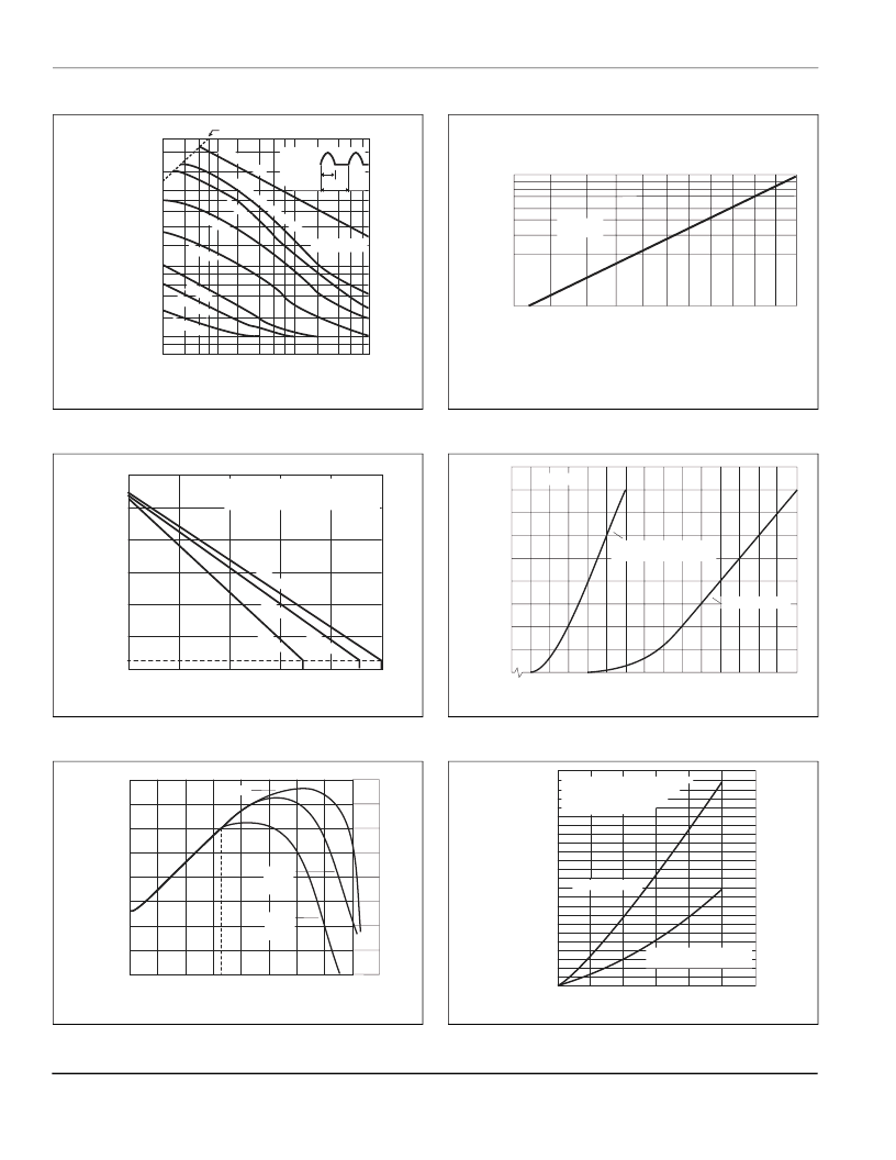
Figure E9.3 Repetitive Peak On-state Current (I
TRM
) versus
Pulse Width at Various Frequencies
Figure E9.4 Maximum Allowable Ambient Temperature versus
On-state Current
Figure E9.5 Normalized V
BO
Change versus Junction Temperature
Figure E9.6 Normalized Repetitive Peak Breakover Current versus
Junction Temperature
Figure E9.7 On-state Current versus On-state Voltage (Typical)
Figure E9.8 Power Dissipation (Typical) versus On-state Current
[Refer to Figure E9.14 for Basic Sidac Circuit]
di/dt Limit Line
0.6
0.8
4
2
4
6
8
10
20
40
60
80
100
200
400
600
2 x 10⁻³
6 8
1 x 10⁻²
Pulse base width (t
o
) – ms
2
4
6 8
1 x 10⁻¹
2
4 6 81
1
R
O
T
)
V
Firing
f=10Hz
f = 100 Hz
f = 1 kHz
f = 5 kHz
f = 10 kHz
f = 20 kHz
T
J
= 125 oC Max
to
ITRM
l/f
Non-Repeated
0
0.2
0.4
0.6
0.8
1.0
20
40
60
80
100
120
140
25
RMS On-state Current [I
T(RMS)
] – Amps
M
A
)
CURRENT WAVEFORM: Sinusoidal - 60 Hz
LOAD: Resistive or Inductive
FREE AIR RATING
TO92andDO214
TO-202Type1
-12
-20
0
+20
+40
+60
+80
+100
+120
-10
-8
-6
-4
-2
0
+2
+4
-40
+25
Junction Temperature (T
J
) – C
P
B
+140
K2xxxF1
K1xxxE
K1xxxG
K1xxxS
K2xxxE
K2xxxG
K2xxxS
20
30
40
50
60
80
70
90
100
110 120
1
2
3
4
5
6
7
8
9
Junction Temperature (T
J
) –
C
R
C
B
)
V = V
BO
130
0
0.8
1.2
1.0
1.4
1.6
1.8
2.0
2.2
2.4
2.6
2.8
3.0
3.2
3.4
3.6
0
1
2
3
4
5
6
7
8
9
Positive or Negative Instantaneous On-state Voltage (v
T
) – Volts
P
O
T
)
TL = 25 C
TO-92, DO-214 and DO-15X
"E", "S" and "G" Packages
TO-202 "F" Package
0.2
0.4
0.6
0.8
1.0
0
0.4
0.8
1.2
1.6
0.2
0.6
1.0
1.4
1.8
2.0
2.2
RMS On-state Current [I
T(RMS)
] – Amps
A
P
D
]
"E", "S" and "G" Packages
TO-92, DO-214 and DO-15X
TO-202 "F" Package
CURRENT WAVEFORM: Sinusoidal
LOAD: Resistive or Inductive
CONDUCTION ANGLE:
See Basic Sidac Cirucit
相關PDF資料 |
PDF描述 |
|---|---|
| BT136F-600E | Thyristor Product Catalog |
| BT136F-600F | Thyristor Product Catalog |
| BT136F-600G | Thyristor Product Catalog |
| BT136F-800 | Thyristor Product Catalog |
| BT136F-800F | Thyristor Product Catalog |
相關代理商/技術參數 |
參數描述 |
|---|---|
| BT136F-600E | 制造商:TECCOR 制造商全稱:TECCOR 功能描述:Thyristor Product Catalog |
| BT136F-600F | 制造商:TECCOR 制造商全稱:TECCOR 功能描述:Thyristor Product Catalog |
| BT136F-600G | 制造商:TECCOR 制造商全稱:TECCOR 功能描述:Thyristor Product Catalog |
| BT136F700 | 制造商:未知廠家 制造商全稱:未知廠家 功能描述:TRIAC|700V V(DRM)|4A I(T)RMS|SOT-186 |
| BT136F700E | 制造商:未知廠家 制造商全稱:未知廠家 功能描述:TRIAC|700V V(DRM)|4A I(T)RMS|SOT-186 |
發(fā)布緊急采購,3分鐘左右您將得到回復。