- 您現(xiàn)在的位置:買(mǎi)賣(mài)IC網(wǎng) > PDF目錄369508 > BT136B_SERIES_E Transient Voltage Suppressor Diodes PDF資料下載
參數(shù)資料
| 型號(hào): | BT136B_SERIES_E |
| 元件分類(lèi): | TVS-瞬態(tài)抑制二極管 |
| 英文描述: | Transient Voltage Suppressor Diodes |
| 中文描述: | 雙向敏感門(mén) |
| 文件頁(yè)數(shù): | 145/224頁(yè) |
| 文件大?。?/td> | 2697K |
| 代理商: | BT136B_SERIES_E |
第1頁(yè)第2頁(yè)第3頁(yè)第4頁(yè)第5頁(yè)第6頁(yè)第7頁(yè)第8頁(yè)第9頁(yè)第10頁(yè)第11頁(yè)第12頁(yè)第13頁(yè)第14頁(yè)第15頁(yè)第16頁(yè)第17頁(yè)第18頁(yè)第19頁(yè)第20頁(yè)第21頁(yè)第22頁(yè)第23頁(yè)第24頁(yè)第25頁(yè)第26頁(yè)第27頁(yè)第28頁(yè)第29頁(yè)第30頁(yè)第31頁(yè)第32頁(yè)第33頁(yè)第34頁(yè)第35頁(yè)第36頁(yè)第37頁(yè)第38頁(yè)第39頁(yè)第40頁(yè)第41頁(yè)第42頁(yè)第43頁(yè)第44頁(yè)第45頁(yè)第46頁(yè)第47頁(yè)第48頁(yè)第49頁(yè)第50頁(yè)第51頁(yè)第52頁(yè)第53頁(yè)第54頁(yè)第55頁(yè)第56頁(yè)第57頁(yè)第58頁(yè)第59頁(yè)第60頁(yè)第61頁(yè)第62頁(yè)第63頁(yè)第64頁(yè)第65頁(yè)第66頁(yè)第67頁(yè)第68頁(yè)第69頁(yè)第70頁(yè)第71頁(yè)第72頁(yè)第73頁(yè)第74頁(yè)第75頁(yè)第76頁(yè)第77頁(yè)第78頁(yè)第79頁(yè)第80頁(yè)第81頁(yè)第82頁(yè)第83頁(yè)第84頁(yè)第85頁(yè)第86頁(yè)第87頁(yè)第88頁(yè)第89頁(yè)第90頁(yè)第91頁(yè)第92頁(yè)第93頁(yè)第94頁(yè)第95頁(yè)第96頁(yè)第97頁(yè)第98頁(yè)第99頁(yè)第100頁(yè)第101頁(yè)第102頁(yè)第103頁(yè)第104頁(yè)第105頁(yè)第106頁(yè)第107頁(yè)第108頁(yè)第109頁(yè)第110頁(yè)第111頁(yè)第112頁(yè)第113頁(yè)第114頁(yè)第115頁(yè)第116頁(yè)第117頁(yè)第118頁(yè)第119頁(yè)第120頁(yè)第121頁(yè)第122頁(yè)第123頁(yè)第124頁(yè)第125頁(yè)第126頁(yè)第127頁(yè)第128頁(yè)第129頁(yè)第130頁(yè)第131頁(yè)第132頁(yè)第133頁(yè)第134頁(yè)第135頁(yè)第136頁(yè)第137頁(yè)第138頁(yè)第139頁(yè)第140頁(yè)第141頁(yè)第142頁(yè)第143頁(yè)第144頁(yè)當(dāng)前第145頁(yè)第146頁(yè)第147頁(yè)第148頁(yè)第149頁(yè)第150頁(yè)第151頁(yè)第152頁(yè)第153頁(yè)第154頁(yè)第155頁(yè)第156頁(yè)第157頁(yè)第158頁(yè)第159頁(yè)第160頁(yè)第161頁(yè)第162頁(yè)第163頁(yè)第164頁(yè)第165頁(yè)第166頁(yè)第167頁(yè)第168頁(yè)第169頁(yè)第170頁(yè)第171頁(yè)第172頁(yè)第173頁(yè)第174頁(yè)第175頁(yè)第176頁(yè)第177頁(yè)第178頁(yè)第179頁(yè)第180頁(yè)第181頁(yè)第182頁(yè)第183頁(yè)第184頁(yè)第185頁(yè)第186頁(yè)第187頁(yè)第188頁(yè)第189頁(yè)第190頁(yè)第191頁(yè)第192頁(yè)第193頁(yè)第194頁(yè)第195頁(yè)第196頁(yè)第197頁(yè)第198頁(yè)第199頁(yè)第200頁(yè)第201頁(yè)第202頁(yè)第203頁(yè)第204頁(yè)第205頁(yè)第206頁(yè)第207頁(yè)第208頁(yè)第209頁(yè)第210頁(yè)第211頁(yè)第212頁(yè)第213頁(yè)第214頁(yè)第215頁(yè)第216頁(yè)第217頁(yè)第218頁(yè)第219頁(yè)第220頁(yè)第221頁(yè)第222頁(yè)第223頁(yè)第224頁(yè)

Application Notes
AN1004
2002 Teccor Electronics
Thyristor Product Catalog
AN1004 - 3
http://www.teccor.com
+1 972-580-7777
Allow for adequate ventilation. If possible, route heat sinks to out-
side of assembly for maximum airflow.
Mounting Surface Selection
Proper mounting surface selection is essential to efficient trans-
fer of heat from the semiconductor device to the heat sink and
from the heat sink to the ambient. The most popular heat sinks
are flat aluminum plates or finned extruded aluminum heat sinks.
The mounting surface should be clean and free from burrs or
scratches. It should be flat within 0.002 inch per inch, and a sur-
face finish of 30 to 60 microinches is acceptable. Surfaces with a
higher degree of polish do not produce better thermal conductiv-
ity.
Many aluminum heat sinks are black anodized to improve ther-
mal emissivity and prevent corrosion. Anodizing results in high
electrical but negligible thermal insulation. This is an excellent
choice for isolated TO-220 devices. For applications of TO-202
devices where electrical connection to the common anode tab is
required, the anodization should be removed. Iridite or chromate
acid dip finish offers low electrical and thermal resistance. Either
TO-202 or isolated TO-220 devices may be mounted directly to
this surface, regardless of application. Both finishes should be
cleaned prior to use to remove manufacturing oils and films.
Some of the more economical heat sinks are painted black. Due
to the high thermal resistance of paint, the paint should be
removed in the area where the semiconductor is attached.
Bare aluminum should be buffed with #000 steel wool and fol-
lowed with an acetone or alcohol rinse. Immediately, thermal
grease should be applied to the surface and the device mounted
down to prevent dust or metal particles from lodging in the critical
interface area.
For good thermal contact, the use of thermal grease is essential
to fill the air pockets between the semiconductor and the mount-
ing surface. This decreases the thermal resistance by 20%. For
example, a typical TO-220 with R
θ
JC
of 1.2 °C/W may be lowered
to 1 °C/W by using thermal grease.
Teccor recommends Dow-Corning 340 as a proven effective ther-
mal grease. Fibrous applicators are not recommended as they
may tend to leave lint or dust in the interface area. Ensure that
the grease is spread adequately across the device mounting sur-
face, and torque down the device to specification.
Contact Teccor Applications Engineering for assistance in choos-
ing and using the proper heat sink for specific application.
Hardware And Methods
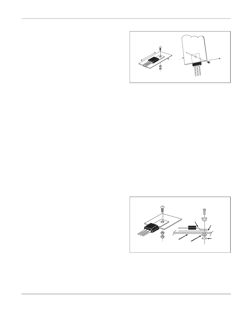
TO-220
The mounting hole for the Teccor TO-220 devices should not
exceed 0.140” (6/32) clearance. (Figure AN1004.7) No insulating
bushings are needed for the L Package (isolated) devices as the
tab is electrically isolated from the semiconductor chip. 6/32
mounting hardware, especially round head or Fillister machine
screws, is recommended and should be torqued to a value of
6 inch-lbs.
Figure AN1004.7
TO-220 Mounting
Punched holes are not acceptable due to cratering around the
hole which can cause the device to be pulled into the crater by
the fastener or can leave a significant portion of the device out of
contact with the heat sink. The first effect may cause immediate
damage to the package and early failure, while the second can
create higher operating temperatures which will shorten operat-
ing life. Punched holes are quite acceptable in thin metal plates
where fine-edge blanking or sheared-through holes are
employed.
Drilled holes must have a properly prepared surface. Excessive
chamfering is not acceptable as it may create a crater effect.
Edges must be deburred to promote good contact and avoid
puncturing isolation materials.
For high-voltage applications, it is recommended that only the
metal portion of the TO-220 package (as viewed from the bottom
of the package) be in contact with the heat sink. This will provide
maximum oversurface distance and prevent a high voltage path
over the plastic case to a grounded heat sink.
TO-202
The mounting hole for the Teccor TO-202 devices should not
exceed 0.112” (4/40) clearance. (Figure AN1004.8) Since tab is
electrically common with anode, heat sink may or may not need
to be electrically isolated from tab. If not, use 4/40 screw with
lock washer and nut. Mounting torque is 6 inch-lbs.
Figure AN1004.8
TO-202 Mounting
A nylon bushing and mica insulation are required to insulate the
tab in an isolated application. A compression washer is recom-
mended to avoid damage to the bushing. Do not attempt to
mount non-formed tabs to a plane surface, as the resulting strain
on the case may cause it or the semiconductor chip assembly to
fail. Teccor has the facilities and expertise to properly tab form
TO-202 devices for the convenience of the consumer.
Lockwasher
6-32 Nut
Heatsink
*
Mounting
screw
6-32
* Screw head must not touch
the epoxy body of the device
Avodaxa sress
exposed metal tab
On heavy aluminum heatsinks
High potential appication
using Isolated TO-220
Heat Sink
at Case
Potential
A
Heat Sink
Compression
Washer
Nut
Appropriate
Screw
4/40 Nylon
Bushing
Mica
Insulator
Tab
Form
B
相關(guān)PDF資料 |
PDF描述 |
|---|---|
| BT136F700G | Transient Voltage Suppressor Diodes |
| BT136MSERIES | Transient Voltage Suppressor Diodes |
| BT136MSERIESD | Transient Voltage Suppressor Diodes |
| BT136S_SERIES | Triacs |
| BT136S_SERIES_D | Triacs logic level |
相關(guān)代理商/技術(shù)參數(shù) |
參數(shù)描述 |
|---|---|
| BT136D | 制造商:CDIL 制造商全稱(chēng):Continental Device India Limited 功能描述:TRIAC |
| BT136-D | 制造商:SEMIWELL 制造商全稱(chēng):SEMIWELL 功能描述:Bi-Directional Triode Thyristor |
| BT136E | 制造商:UTC-IC 制造商全稱(chēng):UTC-IC 功能描述:TRIACS |
| BT136F | 制造商:PHILIPS 制造商全稱(chēng):NXP Semiconductors 功能描述:Triacs |
| BT136F-500 | 制造商:TECCOR 制造商全稱(chēng):TECCOR 功能描述:Thyristor Product Catalog |
發(fā)布緊急采購(gòu),3分鐘左右您將得到回復(fù)。