- 您現(xiàn)在的位置:買賣IC網(wǎng) > PDF目錄373024 > BQ24203DGNR Fast Recovery Bridge Rectifiers PDF資料下載
參數(shù)資料
| 型號(hào): | BQ24203DGNR |
| 英文描述: | Fast Recovery Bridge Rectifiers |
| 中文描述: | 模擬IC |
| 文件頁(yè)數(shù): | 1/14頁(yè) |
| 文件大?。?/td> | 201K |
| 代理商: | BQ24203DGNR |
當(dāng)前第1頁(yè)第2頁(yè)第3頁(yè)第4頁(yè)第5頁(yè)第6頁(yè)第7頁(yè)第8頁(yè)第9頁(yè)第10頁(yè)第11頁(yè)第12頁(yè)第13頁(yè)第14頁(yè)
SLUS501A – OCTOBER 2001
1
www.ti.com
FEATURES
Designed Specifically to Work With
Current-Limited Wall Supplies
Ideal for Low Dropout Charger Design for
Single-Cell Li-Ion Packs With Coke or
Graphite Anodes
Integrated PowerFET for 500 mA
Integrated Voltage Regulation With 0.5%
Accuracy
Battery Insertion and Removal Detection
Charge Termination by Minimum Current and
Time
Pre-Charge Conditioning With Safety Timer
Sleep Mode for Low-Power Consumption
Charge Status Output for LED or Host
Processor Interface Indicates
Charge-in-Progress, Charge Completion, and
Fault Conditions
Optional Temperature Monitoring Before and
During Charge
Small, 8-Pin Power-Pad MSOP Package
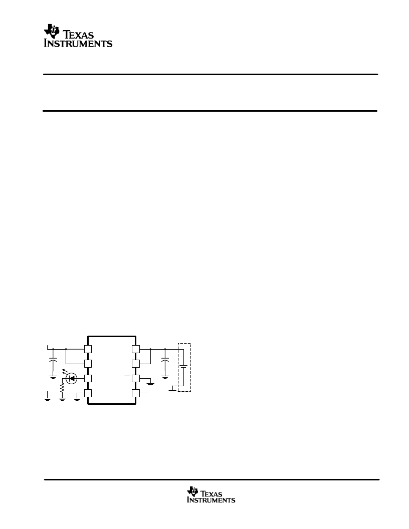
TYPICAL APPLICATION
DESCRIPTION
The bq2420x series are simple Li-Ion linear charge
management devices targeted at low-cost and space
limited charger applications. The bq2420x series offer
integrated
powerFET,
regulation, temperature monitoring, charge status, and
charge termination, in a single monolithic device.
high-accuracy
voltage
The bq2420x is designed to work with a current-limited
wall-mount transformer and therefore does not provide
any current regulation. However, these devices offer a
fixed internal current limit to prevent damage to the
internal powerFET. A time-limited pre-conditioning
phase is provided to condition deeply discharged cells.
Once the battery reaches the charge voltage, the high
accuracy voltage regulation loop takes over and
completes the charge cycle. Charge is terminated
based on minimum current. An internal charge timer
provides a backup safety for charge termination.
Other standard features include an automatic sleep
mode activated when V
CC
falls below the battery
voltage and a recharge feature activated when the
battery voltage falls below the V
RCH
threshold.
In addition to the standard features, the core product
provides two additional enhancements: temperature
monitoring and status display. The temperature-sense
circuit continuously measures battery temperature
using an external thermistor and inhibits charge until the
battery temperature is within the user–defined
thresholds. The STAT pin indicates three conditions of
operation of the charger. These conditions are
charge-
in-progress
,
charge complete
, and
fault
. This output
can be used to drive an LED or an interface to a
microcontroller.
P
!"#$%&" '" '(# ) *#"+,'&) &-( !"#$%&.( "#
+()/ *-%)( "! +(.(0"*$( &1 -%#%'&(#)&'
)*('!'%&" ) %#( +()/ /"%0)1 (2%) )&#,$( &) #()(#.() &-( #/-& &"
'-% /( "# +)'" & ,( &-()( *#"+,'&) 3&-",& "&'(1
+%&% % + "&-(#
Copyright
2001, Texas Instruments Incorporated
1
4
2
8
IN
VCC
VSS
OUT
7
BAT
6
CE
5
N/C
C1
bq24202DGN
3 STAT
DC+
DC–
R1
C1
+
BATTERY PACK
相關(guān)PDF資料 |
PDF描述 |
|---|---|
| BQ24204DGNR | Fast Recovery Bridge Rectifiers |
| BQ24205DGNR | Fast Recovery Bridge Rectifiers |
| BQ24901 | Fast Recovery Bridge Rectifiers |
| BQ2902PN-N | Battery Management |
| BQ2902SN-N | Battery Management |
相關(guān)代理商/技術(shù)參數(shù) |
參數(shù)描述 |
|---|---|
| BQ24203DGNRG4 | 功能描述:電池管理 Single-Chip Li-Ion Charger RoHS:否 制造商:Texas Instruments 電池類型:Li-Ion 輸出電壓:5 V 輸出電流:4.5 A 工作電源電壓:3.9 V to 17 V 最大工作溫度:+ 85 C 最小工作溫度:- 40 C 封裝 / 箱體:VQFN-24 封裝:Reel |
| BQ24204 | 制造商:TI 制造商全稱:Texas Instruments 功能描述:SINGLE CHIP U-I ONAND LI-POL CHARGE MANAGEMENT IC FOR CURRENT LIMITED APPLICATIONS |
| BQ24204DGN | 功能描述:電池管理 Single-Chip Li-Ion Charger RoHS:否 制造商:Texas Instruments 電池類型:Li-Ion 輸出電壓:5 V 輸出電流:4.5 A 工作電源電壓:3.9 V to 17 V 最大工作溫度:+ 85 C 最小工作溫度:- 40 C 封裝 / 箱體:VQFN-24 封裝:Reel |
| BQ24204DGNG4 | 功能描述:電池管理 Single-Chip Li-Ion Charger RoHS:否 制造商:Texas Instruments 電池類型:Li-Ion 輸出電壓:5 V 輸出電流:4.5 A 工作電源電壓:3.9 V to 17 V 最大工作溫度:+ 85 C 最小工作溫度:- 40 C 封裝 / 箱體:VQFN-24 封裝:Reel |
| BQ24204DGNR | 功能描述:電池管理 Single-Chip Li-Ion Charger RoHS:否 制造商:Texas Instruments 電池類型:Li-Ion 輸出電壓:5 V 輸出電流:4.5 A 工作電源電壓:3.9 V to 17 V 最大工作溫度:+ 85 C 最小工作溫度:- 40 C 封裝 / 箱體:VQFN-24 封裝:Reel |
發(fā)布緊急采購(gòu),3分鐘左右您將得到回復(fù)。