- 您現(xiàn)在的位置:買賣IC網(wǎng) > PDF目錄369467 > BH074E0334K KONDENSATOR POLYE RADI 330NF 100V 5ST PDF資料下載
參數(shù)資料
| 型號(hào): | BH074E0334K |
| 英文描述: | KONDENSATOR POLYE RADI 330NF 100V 5ST |
| 中文描述: | KONDENSATOR POLYE拉迪330NF 100V的5ST |
| 文件頁數(shù): | 19/51頁 |
| 文件大小: | 521K |
| 代理商: | BH074E0334K |
第1頁第2頁第3頁第4頁第5頁第6頁第7頁第8頁第9頁第10頁第11頁第12頁第13頁第14頁第15頁第16頁第17頁第18頁當(dāng)前第19頁第20頁第21頁第22頁第23頁第24頁第25頁第26頁第27頁第28頁第29頁第30頁第31頁第32頁第33頁第34頁第35頁第36頁第37頁第38頁第39頁第40頁第41頁第42頁第43頁第44頁第45頁第46頁第47頁第48頁第49頁第50頁第51頁

PERFORMANCE CHARACTERISTICS
APPLICATIONS
Non-inductive, self-healing, metallized polyester film capacitor.
Insulated*thermoplastic casing, epoxy resin sealed with
stand-offs* Radial connections.
*Flame retardant resin and case according to UL 94 VO .
Some examples of use:
Supply decoupling, filter integrators, treatment of analog-
signals, rejection of line perturbations, etc.
STANDARDIZATION
Generic specifications:
CEI 384-1/CECC 30000/UTE 83100
Sectional specifications:
CEI 384-2/CECC 30400/UTE 83151
On the LNZ list:
Complies with type CPM85 – CPM-R
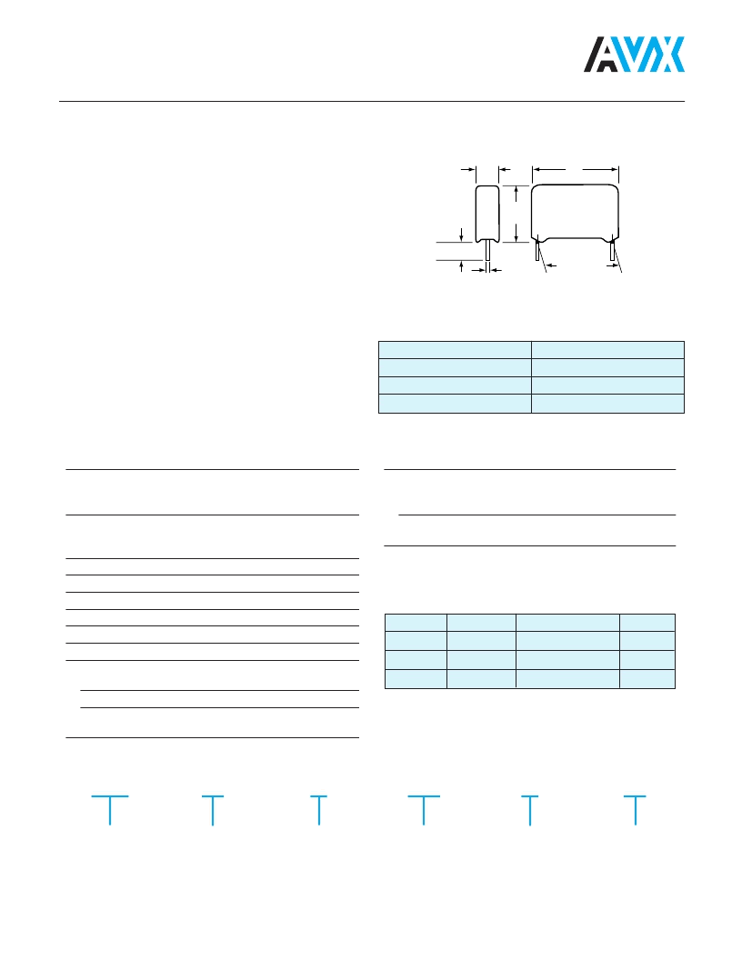
18
T PC
H
Max
e
d
LS
±
0.4
(0.016)
6.
1
(0.024)
L
Protection:
Plastic casing, epoxy resin
sealed flame retardant case
(UL 94 VO)
-55°C to +100°C with voltage
derating of 1.25%/°C between
85°C and 100°C
55/100/56
63 VDC to 1000 VDC
1 nF to 22 μF
±5%, ±10%, ±20%
1.6 Vn/2 s
Temperature range:
Climatic category:
Voltage range:
Capacitance range:
Tolerances on C
R
:
Test voltage:
Insulation resistance:
Measurement condition:
Temperature:
Duration:
Measurement Voltage:
25°C ± 5°C
1 minute
100 V for Vn
≥
100 V
50 V for Vn < 100 V
Requirements:
For Un
≤
100 V:
C
≤
0.33 μF
≥
15,000 M
C > 0.33 μF
≥
C
≤
0.33 μF
≥
30,000 M
C > 0.33 μF
≥
10,000 S
5,000 S
For Un > 100 V:
Tangent of loss angle:
BG 07/10/15/22/27
CPM-85 – 7.5/10/15/22.5/27.5
Boxed Metallized Polyester Capacitor
Lead Spacing (LS)
7.5 (0.295)
10 (0.394)
> 10 (0.394)
Diameter
0.6 (0.024)
0.6
(1)
(0.024) / 0.8 (0.031)
0.8 (0.031)
(1): 0.6 (0.024) for capacitors with e
≤
6 (0.024)
C
≤
0.1 μF
0.1 μF < C
≤
1 μF
C > 1 μF
1 kHz
8 x 10
-3
8 x 10
-3
10 x 10
-3
10 kHz
15 x 10
-3
15 x 10
-3
100 Hz
30 x 10
-3
millimeters (inches)
LIMIT VALUES
MARKING
Logo -
Capacitance
Voltage
Tolerance
HOW TO ORDER
BG 10
Type
Pitch 10mm = 10
Pitch 15mm = 15
Pitch 22.5mm = 22
Pitch 27.5mm = 27
4
Class
G
Voltage
0104
Capacitance Value
K
Tolerance
– –
Suffix
相關(guān)PDF資料 |
PDF描述 |
|---|---|
| BH074E0474K | KONDENSATOR POLYE RADI 470NF 100V 5ST |
| BH10-1-SERIES | Interface IC |
| BH11-1-SERIES | Interface IC |
| BH11-3-SERIES | Interface IC |
| BH11-5-SERIES | Interface IC |
相關(guān)代理商/技術(shù)參數(shù) |
參數(shù)描述 |
|---|---|
| BH074E0474K | 制造商:未知廠家 制造商全稱:未知廠家 功能描述:KONDENSATOR POLYE RADI 470NF 100V 5ST |
| BH074E0474K-- | 制造商:AVX Corporation 功能描述:CAPACITOR 470NF 100V |
| BH074E0474K | 制造商:AVX Corporation 功能描述:CAPACITOR 470NF 100V |
| BH075 | 制造商:ADAM-TECH 制造商全稱:Adam Technologies, Inc. 功能描述:BATTERY HOLDERS & SNAPS AA, AAA, C, D & COIN CELL |
| BH-08 | 制造商:ADAM-TECH 制造商全稱:Adam Technologies, Inc. 功能描述:BATTERY HOLDERS AA SINGLE & MULTIPLE CELLS |
發(fā)布緊急采購,3分鐘左右您將得到回復(fù)。