- 您現(xiàn)在的位置:買賣IC網(wǎng) > PDF目錄166398 > BA7644AN (Rohm CO.,LTD.) 5V High-Speed RS-232 Transceivers with 0.1uF Capacitors PDF資料下載
參數(shù)資料
| 型號(hào): | BA7644AN |
| 廠商: | Rohm CO.,LTD. |
| 元件分類: | RS-232 |
| 英文描述: | 5V High-Speed RS-232 Transceivers with 0.1uF Capacitors |
| 中文描述: | 5V的高速RS - 232收發(fā)器與0.1uF電容 |
| 文件頁(yè)數(shù): | 4/5頁(yè) |
| 文件大小: | 67K |
| 代理商: | BA7644AN |
4
Multimedia ICs
BA7644AN
Measurement conditions
SW1
SW2
SW3
SW4
SW5
SW6
SW7
ICC
2222222
IN 1
IN 2
IN 3
IN 4
Vom
1
2
1
2
1
2
1
3
2
3
2
3
2
3
IN1
IN2
IN3
IN4
GV
1
2
1
2
1
2
1
3
2
3
2
3
2
3
IN1
→IN3
IN1
→IN4
IN1
→MUTE
IN2
→IN3
IN2
→IN4
IN2
→MUTE
IN3
→IN4
IN3
→MUTE
IN4
→MUTE
IN1
→IN2
CT
1
2
1
2
1
2
1
3
2
2
2
2
3
2
3
2
2
3
2
3
2
3
2
IN 1
IN 2
IN 3
IN 4
Gf
1
2
1
2
1
2
1
3
2
3
2
3
2
3
VIN = 1VP-P
IN 1
IN 2
IN 3
IN 4
THD
1
2
1
2
1
2
1
3
2
3
2
3
2
3
f = 1kHz
IN 1
IN 2
IN 3
IN 4
ZIN
3
2
3
2
3
2
3
2
3
2
3
2
3
VTH
2
1
2
1
2
1
2
1
3
1
3
1
VIN = 1VP-P
CTL - A
CTL - B
CTL - C
f = 1kHz,
THD = 0.5%
f = 1MHz,
VIN = 1VP-P
f = 4.43MHz,
f = 10MHz / f = 1MHz
VIN = 1VP-P
Vom
Anywhere is possible.
Note 1: Connect a distortion meter to the output, and input a f = 1kHz sine wave. Adjust the input level until the output distortion is 0.5%.
This output voltage at this time is the maximum output level Vom (VP-P).
Note 2: Input a 1VP-P, 1MHz sine wave. The voltage gain is given by GV = 20 log (VOUT / VIN).
Note 3: Input a 1VP-P, 4.43MHz sine wave. The interchannel crosstalk is given by CT = 20 log (VOUT / VIN).
Note 4: Input 1VP-P, 1MHz and 10MHz sine waves. The frequency characteristic is given by Gf = 20 log (VOUT (f = 10MHz) / VOUT (f = 1MHz)).
Note 5: Input a 1VP-P, 1MHz sine wave and measure the total-harmonic distortion of the output using a total-harmonic distortion meter.
Note 6: Measure the input pin voltage VIN50 when a current of DC50
A is flowing into the input pin. Measure the input pin open-circuit voltage.
The input impedance is given by Z = (VIN50 - VIN0) / 50
× 10-6 [].
Note 7: Input a 1VP-P, 1MHz sine wave. Reduce the CTL pin voltage from VCC.
The CTL pin switching level (VTH) is the CTL pin voltage at which the VOUT level drops below 20mVP-P.
Note 8: Input a 1VP-P, 1MHz sine wave. Increase the CTL pin voltage from 0V.
The CTL pin switching level (VTH) is the CTL pin voltage at which the VOUT level goes above 1.0VP-P.
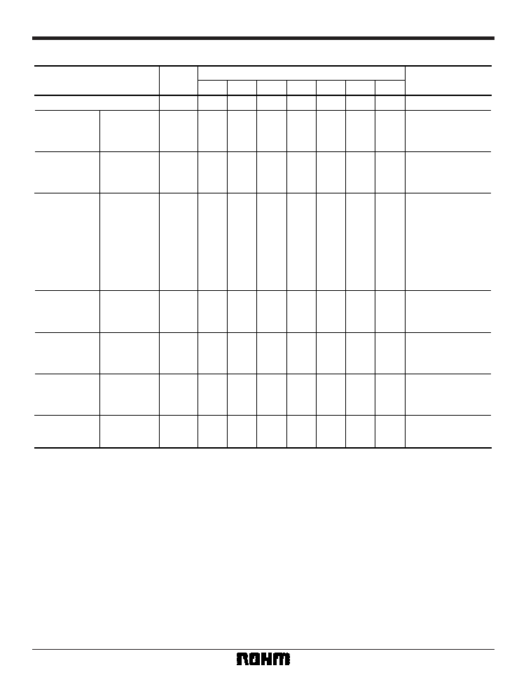
Parameter
Symbol
Switch settings
Measurement method
Current dissipation
Ammeter
Maximum
output level
Note 1
Voltage gain
Note 2
Interchannel
crosstalk
Note 3
Frequency
characteristic
Note 4
Total-harmonic
distortion
Note 5
Input
impedance
Note 6
CTL pin
switching level
Note 7
Note 8
相關(guān)PDF資料 |
PDF描述 |
|---|---|
| BA7645N | 5V High-Speed RS-232 Transceivers with 0.1uF Capacitors |
| BA7649 | Video signal switcher |
| BA7649A | Voltage Output Temperature Sensor with Signal Conditioning; Package: SOIC; No of Pins: 8; Temperature Range: Commercial |
| BA7649AF | Voltage Output Temperature Sensor with Signal Conditioning; Package: SOIC; No of Pins: 8; Temperature Range: Commercial |
| BA7655A | Dual Voltage-controlled Amplifier |
相關(guān)代理商/技術(shù)參數(shù) |
參數(shù)描述 |
|---|---|
| BA7645 | 制造商:ROHM 制造商全稱:Rohm 功能描述:Video signal switcher |
| BA7645N | 制造商:ROHM 制造商全稱:Rohm 功能描述:Video signal switcher |
| BA7649 | 制造商:ROHM 制造商全稱:Rohm 功能描述:Video signal switcher |
| BA7649A | 制造商:ROHM 制造商全稱:Rohm 功能描述:Video signal switcher |
| BA7649A/AF | 制造商:未知廠家 制造商全稱:未知廠家 功能描述:マルチメディアLSI |
發(fā)布緊急采購(gòu),3分鐘左右您將得到回復(fù)。