- 您現(xiàn)在的位置:買賣IC網(wǎng) > PDF目錄295137 > BA15DD0WT-TR 1.5 V FIXED POSITIVE LDO REGULATOR, 0.7 V DROPOUT, SFM5 PDF資料下載
參數(shù)資料
| 型號: | BA15DD0WT-TR |
| 元件分類: | 固定正電壓單路輸出LDO穩(wěn)壓器 |
| 英文描述: | 1.5 V FIXED POSITIVE LDO REGULATOR, 0.7 V DROPOUT, SFM5 |
| 封裝: | LEAD FREE, TO-220FP, 5 PIN |
| 文件頁數(shù): | 5/9頁 |
| 文件大小: | 1047K |
| 代理商: | BA15DD0WT-TR |

5/8
Vcc
CTL
39kΩ
2kΩ
31kΩ
CTL
25kΩ
OUT
R2
R1
Vcc
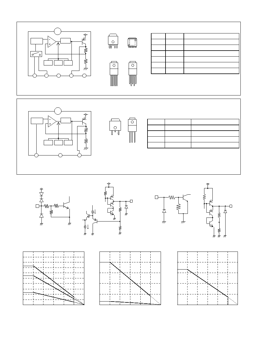
●Block Diagrams
BA□□CC0WFP/ BA□□DD0WHFP/ BA□□CC0WT(V5)/ BA□□DD0WT
BA□□CC0T/ BA□□CC0FP/ BA□□DD0T
Fig.26
●Input / Output Equivalent Circuit Diagrams
< BA□□DD0 Series >
< BA□□CC0 Series >
Fig.27
Fig.28
●Thermal Design
HRP-5
TO220FP-5
TO252-5
Fig.29
Fig.30
Fig.31
When using at temperatures over Ta=25℃, please refer to the heat reducing characteristics shown in Fig.29 through 31. The IC
characteristics are closely related to the temperature at which the IC is used and if the temperature exceeds the maximum
junction temperature TjMAX., the elements may be damaged or destroyed. From the standpoints of instantaneous destruction and
long-term operating reliability, it is necessary give sufficient consideration to IC heat. In order to protect the IC from thermal
damage, it is necessary to operate it at temperatures lower than the maximum junction temperature TjMAX of the IC.
PIN No.
Pin Name
Function
1
CTL
Output voltage ON/OFF control
2
Vcc
Power supply voltage input
3
N.C/GND
Unconnected terminal/GND
*
1
4
OUT
Voltage output
5
N.C
Unconnected terminal
Fin
GND
*
2
PIN No.
Pin Name
Function
1
Vcc
Power supply voltage input
2
N.C/GND
Unconnected terminal/GND*
1
3
OUT
Voltage output
Fin
GND
*
2
Fig.25
HRP5
1 2 3 45
TOP VIEW
TO220FP-5
TO220FP-5(V5)
1 2 3 4 5
TOP VIEW
FIN
TO252-5
1 2 3 4 5
10kΩ
OUT
R2
R1
Vcc
GND
1
2
3
4
5
Fin
Vcc
Driver
OVP
TSD
OCP
R2
R1
CTL
Vcc
N.C.
OUT
N.C.
(TO252-5)
GND
(TO220FP-5,-5(V5),HRP5)
Vref
(TO252-5HRP5)
*2
Only for TO252-5 and HRP5
*1 TO252-5 is N.C.,and TO220FP-5,-5(V5),and HRP5 are GND
*1 TO252-3 is N.C.,and TO-220FP-3,is GND
*2
Only for TO252-3 and HRP5
TOP VIEW
TO220FP-3
2
3
TO252-3
1
FIN
2 3
1
(TO220FP-3)
1
2
3
Fin
Vcc
Driver
OVP
TSD
OCP
R2
R1
Vcc
N.C.
OUT
(TO252-3)
GND
Vref
GND
(TO252-3)
TOP VIEW
0.0
0.4
0.8
1.2
1.6
2.0
0
25
50
75
100
125
150
Ambient temperature:Ta(℃)
Po
w
e
r
D
issi
pa
ti
o
n
:P
d(
W
)
0
1
2
3
4
5
6
7
8
9
10
0
25
50
75
100
125
150
Ambient temperature:Ta(℃)
Po
wer
Di
ss
ip
ati
o
n
:Pd
(W
)
0
5
10
15
20
25
0
25
50
75
100
125
150
Ambient temperature:Ta(℃)
Po
wer
Di
ss
ip
ati
o
n
:Pd
(W
)
③7.3W
②5.5W
①2.3W
(1)20.0
(2)2.0
1.30
Board size : 70×70×1.6 ㎜
3 (board contains a thermal via)
Board front copper foil area : 10.5×10.5 ㎜
2
①2-layer board (back surface copper foil area :15×15 ㎜ 2)
②2-layer board (back surface copper foil area :70×70 ㎜ 2)
③4-layer board (back surface copper foil area :70×70 ㎜ 2)
(1)
When using a maximum heat sick : θj-c=6.25(℃/W)
(2)
When using an IC alone : θj-6=62.5(℃/W)
Mounted on a Rohm standard board
Board size : 70×70×1.6 ㎜
Copper foil area :7×7 ㎜
TO252-5θja=96.2(℃/W)
相關(guān)PDF資料 |
PDF描述 |
|---|---|
| BA08CC0T-E2 | 8 V FIXED POSITIVE LDO REGULATOR, 0.5 V DROPOUT, SFM3 |
| BA08CC0WFP-TR | 8 V FIXED POSITIVE LDO REGULATOR, 0.5 V DROPOUT, PSSO5 |
| BA08CC0WT-TR | 8 V FIXED POSITIVE LDO REGULATOR, 0.5 V DROPOUT, SFM5 |
| BA18BC0FP | 1.8 V FIXED POSITIVE LDO REGULATOR, PSSO2 |
| BA00BC0WFP | 1.5 V-12 V ADJUSTABLE POSITIVE LDO REGULATOR, 0.5 V DROPOUT, PSSO4 |
相關(guān)代理商/技術(shù)參數(shù) |
參數(shù)描述 |
|---|---|
| BA15DXXX | 制造商:ALTECH 制造商全稱:Altech corporation 功能描述:30 mm Replacment Filament Bulbs |
| BA-15E15UD | 制造商:未知廠家 制造商全稱:未知廠家 功能描述:LED LIGHT BAR & BAR GRAPH ARRAYS |
| BA15FP | 制造商:未知廠家 制造商全稱:未知廠家 功能描述:Positive Fixed Voltage Regulator |
| BA15FP-E2 | 功能描述:低壓差穩(wěn)壓器 - LDO REGULATOR 15V 1A RoHS:否 制造商:Texas Instruments 最大輸入電壓:36 V 輸出電壓:1.4 V to 20.5 V 回動電壓(最大值):307 mV 輸出電流:1 A 負(fù)載調(diào)節(jié):0.3 % 輸出端數(shù)量: 輸出類型:Fixed 最大工作溫度:+ 125 C 安裝風(fēng)格:SMD/SMT 封裝 / 箱體:VQFN-20 |
| BA-15G15UD | 制造商:未知廠家 制造商全稱:未知廠家 功能描述:LED LIGHT BAR & BAR GRAPH ARRAYS |
發(fā)布緊急采購,3分鐘左右您將得到回復(fù)。