- 您現(xiàn)在的位置:買賣IC網(wǎng) > PDF目錄369371 > B2526 Dual USB High Side Power Switch PDF資料下載
參數(shù)資料
| 型號: | B2526 |
| 英文描述: | Dual USB High Side Power Switch |
| 中文描述: | 雙USB高側(cè)電源開關(guān) |
| 文件頁數(shù): | 2/7頁 |
| 文件大小: | 174K |
| 代理商: | B2526 |

Bay Linear, Inc
2418Armstrong St., Livermore CA USA 94550 Tel: (925) 606-5950, Fax: (925) 940-9556 www.baylinear.com
B2526
ABSOLUTE MAXIMUM RATINGS OPERATING RATING
Supply Voltage…………………………………...6V
Fault Flag Voltage………………………………..6V
Fault Flag Current……………………………..50mA
Output Voltage……………………………………6V
Output Current……………………Internally Limited
Enable Input……………………………-0.3V to 12V
Storage Temperature………………-65
°
C to +150
°
C
Lead Temperature (Soldering 5 sec.)………….260
°
C
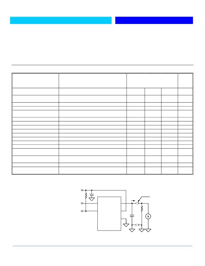
ELECTRICAL CHARACTERISTICS
at V
IN
= 5V, Ta=25
°
C, unless otherwise specified. (Note 1)
Parameters
Conditions
Supply Voltage..................................................+3V to +5.5V
Ambient Operating Temperature....................-40
°
C to +85
°
C
Thermal Resistance
SOIC..................................................................120
°
C/W
DIP.....................................................................130
°
C/W
Typ
Min
Max
5
160
Units
Supply Current
(Note1) Switch Off, OUT = Open
(Note1) Switch On, OUT = Open
Low to High Transition
High to Low Transition, (Note1)
V
EN
= 0V to 5.5V
V
IN
= 5V I
OUT
= 500mA, Each Switch
V
IN
= 3.3V I
OUT
= 500mA, Each Switch
R
L
= 10
R
L
= 10
R
L
= 10
R
L
= 10
Each output (output disabled)
Each output
Each output (enable into load), V
OUT
= 4.0V
Ramped Load applied to enable output, V
OUT
≤
4.0V
T
J
Increasing
T
J
Decreasing
V
IN
= 5.0V, I
L
= 10mA
V
IN
= 3.3V, I
L
= 10mA
V
FLAG
= 5V
V
IN
= Increasing
V
IN
= Decreasing
0.75
110
2.1
1.9
± 0.01
1
100
140
0.5
1
1
1
0.5
0.5
μ
A
Enable Input Threshold
0.8
-1
2.4
V
Enable Input Current
Enable Input Capacitance
Switch Resistance
1
μ
A
pF
140
180
20
20
10
1.25
2.2
m
Output Turn-On Delay
Output Turn-On Rise Time
Output Turn-Off Delay
Output Turn-Off Fall Time
Output Leakage Current
Continuous Load Current
Short Circuit Current Limit
Current Limit Threshold
Over temperature Shutdown
Threshold
Error Flag Output Resistance
ms
ms
μ
s
μ
s
μ
A
A
A
A
0.75
1.6
135
125
10
15
0.01
2.5
2.3
°
C
Error Flag Off Current
UVLO Threshold
1
μ
A
V
General Note: Devices are ESD protected, however, handling precautions recommended.
Note 1: Off is
≤
0.8V and is
≥
2.4V for the B2526-1. Off is
≥
2.4V and on is
≤
0.8V for the B2526-2. The Enable input has approximately 200mV of hysteresis.
TEST CIRCUIT
(Only 1 Output Shown)
Functional Characteristics Test Circuit
EN (A)
FLG (A)
Out (A)
IN
GND
Out (B)
FLG (B)
EN (B)
5V
10K
0.1
μ
F
B2526
I
(for Current
Limit
Response)
R
L
C
L
+
I
OUT
Ferrite
Bead
相關(guān)PDF資料 |
PDF描述 |
|---|---|
| B25667A3127A175 | CAP 1X124UF400V |
| B25667A3207A375 | CAP 3X69UF400V |
| B25667A3247A375 | CAP 3X829UF400V |
| B25667A3337A375 | CAP 3X1108UF480V |
| B25667A3417A375 | CAP 3X138UF400V |
相關(guān)代理商/技術(shù)參數(shù) |
參數(shù)描述 |
|---|---|
| B2526-1M | 制造商:未知廠家 制造商全稱:未知廠家 功能描述:Dual USB High Side Power Switch |
| B2526-1P | 制造商:未知廠家 制造商全稱:未知廠家 功能描述:Dual USB High Side Power Switch |
| B2526-2M | 制造商:未知廠家 制造商全稱:未知廠家 功能描述:Dual USB High Side Power Switch |
| B2526-2P | 制造商:未知廠家 制造商全稱:未知廠家 功能描述:Dual USB High Side Power Switch |
| B2527 | 制造商:Hubbell Wiring Device-Kellems 功能描述:RND CAST FB, STL, DEEP, FULL ADJ,BRS |
發(fā)布緊急采購,3分鐘左右您將得到回復(fù)。