- 您現(xiàn)在的位置:買賣IC網(wǎng) > PDF目錄379689 > ASC7512 (Electronic Theatre Controls, Inc.) DIGITAL TEMPERATURE SENSOR WITH INTEGRATED FAN CONTROL PDF資料下載
參數(shù)資料
| 型號: | ASC7512 |
| 廠商: | Electronic Theatre Controls, Inc. |
| 元件分類: | 溫度/濕度傳感器 |
| 英文描述: | DIGITAL TEMPERATURE SENSOR WITH INTEGRATED FAN CONTROL |
| 中文描述: | 數(shù)字溫度傳感器整合了風(fēng)扇控制 |
| 文件頁數(shù): | 10/35頁 |
| 文件大?。?/td> | 337K |
| 代理商: | ASC7512 |
第1頁第2頁第3頁第4頁第5頁第6頁第7頁第8頁第9頁當(dāng)前第10頁第11頁第12頁第13頁第14頁第15頁第16頁第17頁第18頁第19頁第20頁第21頁第22頁第23頁第24頁第25頁第26頁第27頁第28頁第29頁第30頁第31頁第32頁第33頁第34頁第35頁
Operation
ALERT
Output
- 10 -
Andigilog, Inc. 2006
www.andigilog.com
August 2006 - 70A05003
aSC7512
The aSC7512 has an emergency alarm function,
ALERT
that is optionally assigned to pin 6, the TACH /
ALERT
pin.
ALERT
is determined by both high and low
limits and will also respond to a remote diode open circuit
failure. These limits are settable separately for Zone 1
and Zone 2 sensors. Any alarm condition is reported
individually in the status register and may be read at any
time on the SMBus. Alarm conditions are logically
combined and used to drive an open-drain output, the
ALERT
output, (pin 6).
This output pin may be used as an interrupt signal the
CPU or to turn on remote drivers for fans or indicators.
The
ALERT
pin will remain asserted until it has been
reset by the host via the SMBus.
ALERT
Limits
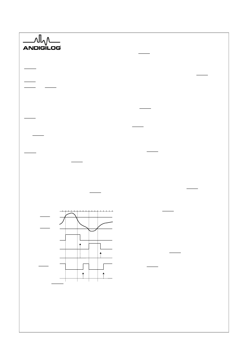
Figure 7 shows use of the
ALERT
high and low limits.
The user sets up the alarm by writing the upper and lower
limit temperatures into the limit registers over the SMBus.
After each measurement, the comparator tests the
readings against the programmed limits and if the
measurement exceeds the high limit is or is equal to or
less-than the low limit, it will assert the particular alarm
bits in the status register and cause the
ALERT
pin to go
low.
Figure 7
ALERT
Limits and Responses
The status bits will remain high until the status register is
read and then, if the condition is no longer present those
bits will be reset, otherwise they will remain high until the
conditions are no longer met and the register is read
again. The same sequence applies to the local readings
and limits.
The
ALERT
pin will remain low until the status bits have
been reset and an Alert Response has been issued by
the master and responded by the aSC7512. This flow is
described below.
The user may mask-out or disable the
ALERT
signal pin
should it be necessary to prevent a processor interrupt.
This is controlled by setting bit 7 of the configuration
register.
SMBus Alert Output
The
ALERT
pin may be used to signal an SMBus Alert to
the host processor. This is a special mode of the SMBus
interface that requires the SMBus host to send an Alert
Response Address (ARA) to all slaves sharing the
ALERT
pin in order to isolate clear and service the
alerting device. This sequence is described below and in
Figure 6.
The sequence of servicing this interrupt is as follows:
1.
ALERT
is asserted by the aSC7512 driving pin
6 low.
2. The SMBus master begins a read operation with
a start followed by the ARA response address,
0001 100. This is an SMBus General Call
Address to be used only for requesting an alert
response.
3. The device providing the
ALERT
signal responds
to this by providing an ACK followed by its own
bus address, an aSC7512 will provide, 101
1000, with the LSB of the data byte set to 1. A
NACK response is expected from all devices not
giving an
ALERT
.
4. If more than one device responds, the device
with the lowest device address will have priority
and will be serviced first by the master.
5. The service routine must read the status register
of the alerting device to determine the nature of
the alert. If the alerting condition is still present,
the status bit will remain set, continuing to
activate the
ALERT
pin. If the condition is
removed, the status bit will be cleared and an
additional
ARA
will
ALERT
pin.
now
de-assert
the
ZN1 Low
ALERT
Limit
Temperature
Conversion
ZN1 High
ALERT
Limit
Status Bit-4, RHIGH
Status Bit-3, RLOW
Status Register Read
ARA Response
ALERT
Pin 6
相關(guān)PDF資料 |
PDF描述 |
|---|---|
| ASC7512D8 | DIGITAL TEMPERATURE SENSOR WITH INTEGRATED FAN CONTROL |
| ASC7512M8 | DIGITAL TEMPERATURE SENSOR WITH INTEGRATED FAN CONTROL |
| ASC7521A | LOW- OLTAGE 1-WIRE DIGITAL TEMPERATURE SENSOR |
| ASC7521AM8 | LOW- OLTAGE 1-WIRE DIGITAL TEMPERATURE SENSOR |
| ASC7531A | LOW-VOLTAGE 1-WIRE DIGITAL TEMPERATURE SENSOR AND VOLTAGE MONITOR |
相關(guān)代理商/技術(shù)參數(shù) |
參數(shù)描述 |
|---|---|
| ASC7512D8 | 制造商:未知廠家 制造商全稱:未知廠家 功能描述:DIGITAL TEMPERATURE SENSOR WITH INTEGRATED FAN CONTROL |
| ASC7512M8 | 制造商:未知廠家 制造商全稱:未知廠家 功能描述:DIGITAL TEMPERATURE SENSOR WITH INTEGRATED FAN CONTROL |
| ASC7521A | 制造商:未知廠家 制造商全稱:未知廠家 功能描述:LOW- OLTAGE 1-WIRE DIGITAL TEMPERATURE SENSOR |
| ASC7521AM8 | 制造商:未知廠家 制造商全稱:未知廠家 功能描述:LOW- OLTAGE 1-WIRE DIGITAL TEMPERATURE SENSOR |
| ASC7531A | 制造商:未知廠家 制造商全稱:未知廠家 功能描述:LOW-VOLTAGE 1-WIRE DIGITAL TEMPERATURE SENSOR AND VOLTAGE MONITOR |
發(fā)布緊急采購,3分鐘左右您將得到回復(fù)。