- 您現(xiàn)在的位置:買賣IC網(wǎng) > PDF目錄362398 > ARM2812T Hi-Rel DC-DC MegaRad-Hard Triple Converter in a ARM package PDF資料下載
參數(shù)資料
| 型號(hào): | ARM2812T |
| 英文描述: | Hi-Rel DC-DC MegaRad-Hard Triple Converter in a ARM package |
| 中文描述: | 高可靠性的DC - DC MegaRad硬三轉(zhuǎn)換器在ARM的包 |
| 文件頁(yè)數(shù): | 7/13頁(yè) |
| 文件大?。?/td> | 94K |
| 代理商: | ARM2812T |
第1頁(yè)第2頁(yè)第3頁(yè)第4頁(yè)第5頁(yè)第6頁(yè)當(dāng)前第7頁(yè)第8頁(yè)第9頁(yè)第10頁(yè)第11頁(yè)第12頁(yè)第13頁(yè)
www.irf.com
7
ARM28XXT Series
to an appropriate heat dissipater held in intimate contact
with the converter base-plate.
Effectiveness of this heat transfer is dependent on the
intimacy of the baseplate-heatsink interface. It is there-
fore suggested that a heat transferring medium possess-
ing good thermal conductivity is inserted between the
baseplate and heatsink. A material utilized at the factory
during testing and burn-in processes is sold under the
trade name of Sil-Pad
4001. This particular product is an
insulator but electrically conductive versions are also avail-
able. Use of these materials assures optimum surface
contact with the heat dissipater by compensating for mi-
nor surface variations. While other available types of heat
conducting materials and thermal compounds provide simi-
lar effectiveness, these alternatives are often less conve-
nient and are frequently messy to use.
A conservative aid to estimating the total heat sink surface
area (A
HEAT SINK
) required to set the maximum case tem-
perature rise (
T) above ambient temperature is given by
the following expression:
A
HEAT SINK
≈
T
P
80
594
.
0 85
.
1 43
.
T
P
P
Eff
OUT
=
=
=
Case temperature rise above ambient
Device dissipation in Watts
1
1
where
As an example, assume that it is desired to maintain the
case temperature of an ARM2815T at +65°C or less while
operating in an open area whose ambient temperature
does not exceed +35°C; then
T = 65 - 35 = 35°C
From the Specification Table, the worst case full load effi-
ciency for this device is 80%; therefore the maximum power
dissipation at full load is given by
(
)
P
=
=
=
30
1
80
.
1
30
025
.
75
. W
and the required heat sink area is
A
=
35
80 7.5
in
HEAT SINK
0.85
=
1 43
.
2
594
.
318
.
1Sil-Pad is a registered Trade Mark of Bergquist, Minneapolis, MN
Thus, a total heat sink surface area (including fins, if any)
of approximately 32 in2 in this example, would limit case
rise to 35°C above ambient. A flat aluminum plate, 0.25"
thick and of approximate dimension 4" by 4" (16 in2 per
side) would suffice for this application in a still air environ-
ment. Note that to meet the criteria, both sides of the plate
require unrestricted exposure to the ambient air.
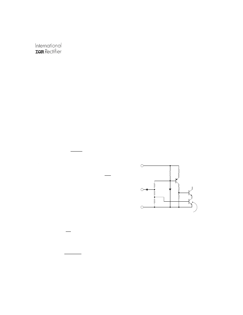
Inhibiting Converter Output
As an alternative to application and removal of the DC
voltage to the input, the user can control the converter
output by providing an input referenced, TTL compatible,
logic signal to the enable pin 3. This port is internally pulled
“high” so that when not used, an open connection on the
pin permits normal converter operation. When inhibited
outputs are desired, a logical “l(fā)ow” on this port will shut the
converter down. An open collector device capable of sink-
ing at least 100 μA connected to enable pin 3 will work well
in this application.
Figure II. Enable Input Equivalent Circuit
A benefit of utilization of the enable input is that following
initial charge of the input capacitor, subsequent turn-on
commands will induce no uncontrolled current inrush.
5K
2N2907A
150K
Enable
Input
Input
Return
150K
2N2222A
2N2222A
V
in
64K
186K
150K
5.6 V
Converter inhibit is initiated when
this transistor is turned off
相關(guān)PDF資料 |
PDF描述 |
|---|---|
| ARM2815T | Hi-Rel DC-DC MegaRad-Hard Triple Converter in a ARM package |
| ARM7TDMI-S | ARM7TDMI-S Microprocessor Core preliminary technical manual 5/00 |
| ARM946E-S | ARM946E-S Microprocessor Core with Cache technical manual 6/01 |
| ARM966E-S | ARM966E-S Microprocessor Core preliminary technical manual 6/01 |
| ARS2569 | Amplifier. Other |
相關(guān)代理商/技術(shù)參數(shù) |
參數(shù)描述 |
|---|---|
| ARM2812T/CK | 制造商:IRF 制造商全稱:International Rectifier 功能描述:HYBRID - HIGH RELIABILITY 1 MEGA-RAD HARDENED DC/DC CONVERTER |
| ARM2812T/EM | 制造商:IRF 制造商全稱:International Rectifier 功能描述:HYBRID - HIGH RELIABILITY 1 MEGA-RAD HARDENED DC/DC CONVERTER |
| ARM2815T | 制造商:未知廠家 制造商全稱:未知廠家 功能描述:Hi-Rel DC-DC MegaRad-Hard Triple Converter in a ARM package |
| ARM2815T/CK | 制造商:IRF 制造商全稱:International Rectifier 功能描述:HYBRID - HIGH RELIABILITY 1 MEGA-RAD HARDENED DC/DC CONVERTER |
| ARM2815T/EM | 制造商:IRF 制造商全稱:International Rectifier 功能描述:HYBRID - HIGH RELIABILITY 1 MEGA-RAD HARDENED DC/DC CONVERTER |
發(fā)布緊急采購(gòu),3分鐘左右您將得到回復(fù)。