- 您現(xiàn)在的位置:買賣IC網(wǎng) > PDF目錄376491 > AN7513S (PANASONIC CORP) BTL Audio Power IC PDF資料下載
參數(shù)資料
| 型號(hào): | AN7513S |
| 廠商: | PANASONIC CORP |
| 元件分類: | 音頻/視頻放大 |
| 英文描述: | BTL Audio Power IC |
| 中文描述: | 0.5 W, 1 CHANNEL, AUDIO AMPLIFIER, PDSO8 |
| 封裝: | 0.225 INCH, PLASTIC, SOP-8 |
| 文件頁數(shù): | 24/25頁 |
| 文件大?。?/td> | 278K |
| 代理商: | AN7513S |

min.
–
–
–
31
–
2.4
30
-250
70
20.5
–
-12
max.
60
10
0.4
35
0.5
–
–
250
–
26.5
–
Parameter
Quiescent current
Standby current
Output noise voltage
Voltage gain
Total harmonic distortion
Maximum power output
Ripple rejection ratio
Output offset voltage
Maximum attenuation
Center voltage gain
Standby terminal current
Volume terminal current
Unit
mA
μ
A
mVrms
dB
%
W
dB
mV
dB
dB
μ
A
μ
A
Symbol
I
CQ
I
STB
V
NO
G
V
THD
P
O
RR
V
off
Att
G
VM
I
STB
I
vol
Condition
V
IN
=0mV,Vol.=0V
V
IN
=0mV,Vol.=0V
Rg=10k
,Vol.=0V
P
O
=0.25W,Vol.=1.25V
P
O
=0.25W,Vol.=1.25V
THD=10%,Vol.=1.25V
Rg=10k
,
Vol.=0V
Vr=0.5Vrms,fr=120Hz
Rg=10k
,Vol.=0V
P
O
=0.5W,Vol=0V
P
O
=0.5W,Vol=0.6V
V
IN
=0mV,V
STB
=3V
V
IN
=0mV,Vol=0V
I
Electrical Characteristics (Vcc=5.0V,R
L
=
8
,freq=1kHz,Ta=25
oC
±
2
oC
)
typ.
25
1
0.10
33
0.10
3.0
50
0
85
23.5
–
–
Note
1
1
1
Note1) For this measurement,use the filter <Bandwidth:15Hz to 30kHz(12dB/octave)>
I
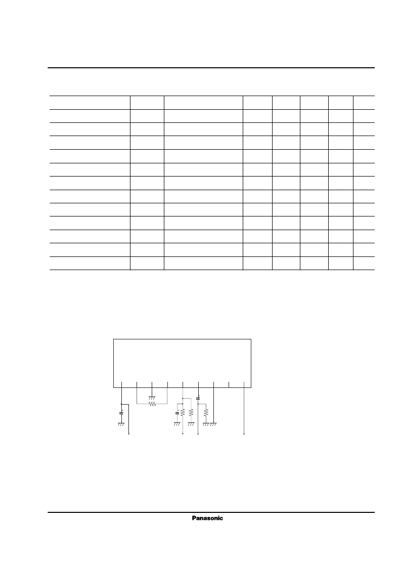
Application Circuit
AN7523
8
Out1
1
μ
F
6
1
2
Standby V
IN1
4
μ
F
V
CC
1
μ
F
Volume
1
2
3
4
5
6
7
8
9
發(fā)布緊急采購,3分鐘左右您將得到回復(fù)。