- 您現(xiàn)在的位置:買賣IC網(wǎng) > PDF目錄378402 > AN-1090 (International Rectifier) Controller Dynamics and Tuning PDF資料下載
參數(shù)資料
| 型號: | AN-1090 |
| 廠商: | International Rectifier |
| 英文描述: | Controller Dynamics and Tuning |
| 中文描述: | 控制器動力學和調(diào)整 |
| 文件頁數(shù): | 13/15頁 |
| 文件大小: | 269K |
| 代理商: | AN-1090 |
15
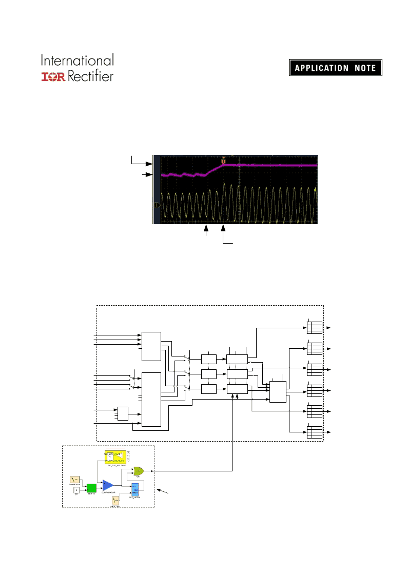
Space Vector PWM) will be set. This will trigger a zero vector (low side devices turn-on) PWM
state independent of any condition (including faults). The use of a zero vector enforces short
circuit to the motor terminal and hence prohibits charging of dc bus capacitors. Figure 19
illustrates critical over voltage condition and the engagement of zero vector protection. Upon
application of the zero vector, motor current will circulate within the motor windings and the
rotational energy of the motor will be dissipated inside the motor (copper and core losses).
Critical dc bus
Over voltage
www.irf.com
13
Motor
W-phase
Current
Hor: 10 msec/ Div
Inverter
Shut down
Zero Vector
initiation
Nominal dc
bus voltage
Figure 19. Critical DC Bus Over Voltage
(top: dc bus voltage, bottom: motor current)
The interface between the critical over voltage detection and the Space Vector PWM module is
shown in Figure 20.
PWMUH
PWMUL
PWMVH
PWMVL
PWMWH
PWMWL
IC Pwm
Pin Outs
Duty
Ratio
Modulator
Space
Vector
Modulator
(SVPWM)
User_Alpha
User_Beta
UserVabEn
From Sensorless FOC
From Sensorless FOC
TwoPhsCtrl[0]
C
2-phase
PWM
Enable
Logic
MotorSpeed
PPwm2HiThr
PwmPeriodConfig
User_U
User_V
User_W
Guard
Band
Protect
Gate
Mux
Guard
Band
Protect
Gate
Mux
Guard
Band
Protect
Gate
Mux
UserVuvwEn
u
v
w
u
v
w
PwmGuardBand
PwmDeadTm
pwmcfg[2]
pwmcfg[3]
Bootstrap
Precharge
GCChargePW
GCChargePD
pwmCtrl
= input
= "Z"
= "0"
= "1"
00
01
10
11
port_Ctrl0[3:2]
= input
= "Z"
= "0"
= "1"
00
01
10
11
port_Ctrl0[1:0]
= input
= "Z"
= "0"
= "1"
00
01
10
11
port_Ctrl0[5:4]
= input
= "Z"
= "0"
= "1"
00
01
10
11
port_Ctrl0[7:6]
= input
= "Z"
= "0"
= "1"
00
01
10
11
port_Ctrl0[9:8]
= input
= "Z"
= "0"
= "1"
00
01
10
11
port_Ctrl0[11:10]
UL
UH
VH
VL
WL
WH
u
v
w
pwm_lines[6]
pwm_lines[8]
pwm_lines[7]
pwm_lines[9]
pwm_lines[10]
pwm_lines[11]
ModScl
TwoPhsCtrl[1]
PwmPeriodConfig
MCE Application
Critical Ov protection
SVPWM module
CriticalOv
Figure 20. Critical Over Voltage Interface
相關(guān)PDF資料 |
PDF描述 |
|---|---|
| AN-1097 | IRS2011 and IR2011 Comparison |
| AN-1192 | broad portfolio of monolithic power integrated circuits covering power levels |
| AN-136 | A NEW GENERATION OF TAG SRAMS?THE IDT71215 AND |
| AN-242 | LJT 18C 18#20 SKT RECP |
| AN-40 | Application Note 40 |
相關(guān)代理商/技術(shù)參數(shù) |
參數(shù)描述 |
|---|---|
| AN-1097 | 制造商:IRF 制造商全稱:International Rectifier 功能描述:IRS2011 and IR2011 Comparison |
| AN10-C06 | 制造商:SMC Corporation of America 功能描述:Silencer, Compact Resin, One-Touch, 6mm Port, 30 dB(A), 36.5mm, Model AN10-C06 |
| AN10C22A | 制造商: 功能描述: 制造商:undefined 功能描述: |
| AN10E40 | 制造商:未知廠家 制造商全稱:未知廠家 功能描述:Field Programmable Analog Array |
| AN10-N01 | 制造商:SMC Corporation of America 功能描述:Silencer, Compact Resin, Male Thread, 1/8" NPT Port, 30 dB(A), Model AN10 |
發(fā)布緊急采購,3分鐘左右您將得到回復。