- 您現(xiàn)在的位置:買賣IC網(wǎng) > PDF目錄362273 > AM29PL142DCB 10MS, 8 SOIC, EXT TEMP, GREEN, 2.7V(SERIAL EE) PDF資料下載
參數(shù)資料
| 型號: | AM29PL142DCB |
| 英文描述: | 10MS, 8 SOIC, EXT TEMP, GREEN, 2.7V(SERIAL EE) |
| 中文描述: | 用戶可編程ASIC的特殊功能 |
| 文件頁數(shù): | 23/67頁 |
| 文件大小: | 635K |
| 代理商: | AM29PL142DCB |
第1頁第2頁第3頁第4頁第5頁第6頁第7頁第8頁第9頁第10頁第11頁第12頁第13頁第14頁第15頁第16頁第17頁第18頁第19頁第20頁第21頁第22頁當(dāng)前第23頁第24頁第25頁第26頁第27頁第28頁第29頁第30頁第31頁第32頁第33頁第34頁第35頁第36頁第37頁第38頁第39頁第40頁第41頁第42頁第43頁第44頁第45頁第46頁第47頁第48頁第49頁第50頁第51頁第52頁第53頁第54頁第55頁第56頁第57頁第58頁第59頁第60頁第61頁第62頁第63頁第64頁第65頁第66頁第67頁
August 8, 2003
Am29PDL129H
21
P R E L I M I N A R Y
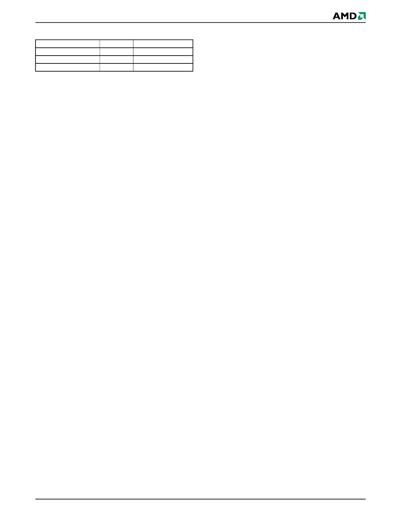
Table 5.
SecSi
TM
Sector Addresses
Autoselect Mode
The autoselect mode provides manufacturer and de-
vice identification, and sector protection verification,
through identifier codes output on DQ7–DQ0. This
mode is primarily intended for programming equip-
ment to automatically match a device to be pro-
grammed with its corresponding programming
algorithm. However, the autoselect codes can also be
accessed in-system through the command register.
When using programming equipment, the autoselect
mode requires V
ID
on address pin A9. Address pins
must be as shown in
Table 6
. In addition, when verify-
ing sector protection, the sector address must appear
on the appropriate highest order address bits (see
Table 4
).
Table 6
shows the remaining address bits
that are don’t care. When all necessary bits have been
set as required, the programming equipment may then
read the corresponding identifier code on DQ7–DQ0.
However, the autoselect codes can also be accessed
in-system through the command register, for instances
when the device is erased or programmed in a system
without access to high voltage on the A9 pin. The
command sequence is illustrated in
Table 14
.
Note
that if a Bank Address (BA) on address bits A21 and
A20 is asserted during the third write cycle of the au-
toselect command, the host system can read autose-
lect data that bank and then immediately read array
data from the other bank, without exiting the autose-
lect mode.
To access the autoselect codes in-system, the host
system can issue the autoselect command via the
command register, as shown in
Table 14
. This method
does not require V
ID
. Refer to the
Autoselect Com-
mand Sequence
section for more information.
Sector Size
128 words
64 words
64 words
Address Range
000000h–00007Fh
000000h-00003Fh
000040h-00007Fh
Am29PDL129H
Factory-Locked Area
Customer-Lockable Area
相關(guān)PDF資料 |
PDF描述 |
|---|---|
| AM29PL160C | 16 Mbit (2 M x 8-Bit/1 M x 16-Bit) CMOS High Performance Page Mode |
| AM29PL160CB-90EI | 5-SOT23, Pb/HALO FREE, 1.8V(SERIAL EE) |
| AM29PL160CB-90REI | DIE SALE, 1.8V, 27MIL(SERIAL EE) |
| AM29PL160CB-90RSI | x8/x16 Flash EEPROM |
| AM29PL160CB-90SI | x8/x16 Flash EEPROM |
相關(guān)代理商/技術(shù)參數(shù) |
參數(shù)描述 |
|---|---|
| AM29PL160CB-90SF | 制造商:Advanced Micro Devices 功能描述: |
| AM29PL160CB-90SI | 制造商:SOCO 功能描述: |
| AM29SL160CT-100EIN | 制造商:Advanced Micro Devices 功能描述: |
| AM29SL800DB120WCI | 制造商:Spansion 功能描述:FLASH PARALLEL 1.8V 8MBIT 1MX8/512KX16 120NS 48FBGA - Trays |
| AM29SL800DB90WAD | 制造商:Spansion 功能描述: |
發(fā)布緊急采購,3分鐘左右您將得到回復(fù)。