- 您現(xiàn)在的位置:買賣IC網(wǎng) > PDF目錄352491 > AM28F512A-90JEB (Advanced Micro Devices, Inc.) Hex Inverters 14-SOIC -40 to 85 PDF資料下載
參數(shù)資料
| 型號: | AM28F512A-90JEB |
| 廠商: | Advanced Micro Devices, Inc. |
| 英文描述: | Hex Inverters 14-SOIC -40 to 85 |
| 中文描述: | 512千比特(64畝× 8位)的CMOS 12.0伏,整體擦除閃存的嵌入式記憶算法 |
| 文件頁數(shù): | 34/34頁 |
| 文件大?。?/td> | 463K |
| 代理商: | AM28F512A-90JEB |
第1頁第2頁第3頁第4頁第5頁第6頁第7頁第8頁第9頁第10頁第11頁第12頁第13頁第14頁第15頁第16頁第17頁第18頁第19頁第20頁第21頁第22頁第23頁第24頁第25頁第26頁第27頁第28頁第29頁第30頁第31頁第32頁第33頁當(dāng)前第34頁
Am28F512A
9
FUNCTIONAL DESCRIPTION
Description Of User Modes
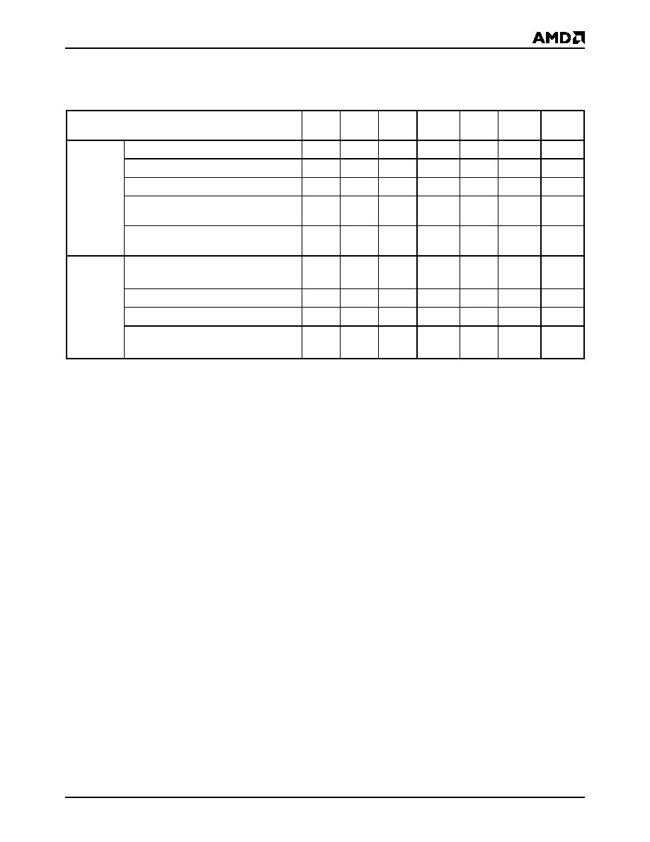
Table 1.
Am28F512A Device Bus Operations (Notes 7 and 8)
Legend:
X = Don’t care, where Don’t Care is either VIL or VIH levels. VPPL = VPP < VCC + 2 V. See DC Characteristics for voltage levels
Notes:
1. VPPL may be grounded, connected with a resistor to ground, or < VCC + 2.0 V. VPPH is the programming voltage specified for
the device. Refer to the DC characteristics. When VPP = VPPL, memory contents can be read but not written or erased.
2. Manufacturer and device codes may also be accessed via a command register write sequence. Refer to Table 2.
3. 11.5 < VID < 13.0 V. Minimum VID rise time and fall time (between 0 and VID voltages) is 500 ns.
4. Read operation with VPP = VPPH may access array data or the Auto select codes.
5. With VPP at high voltage, the standby current is ICC + IPP (standby).
7. All inputs are Don’t Care unless otherwise stated, where Don’t Care is either VIL or VIH levels. In the Auto select mode all
addresses except A9 and A0 must be held at VIL.
8. If VCC ≤ 1.0 Volt, the voltage difference between VPP and VCC should not exceed 10.0 volts. Also, the Am28F256 has a VPP
rise time and fall time specification of 500 ns minimum.
Operation
CE#
(E#)
OE#
(G#)
WE#
(W#)
VPP
(Note 1)
A0
A9
I/O
Read-Only
Read
VIL
XVPPL
A0
A9
DOUT
Standby
VIH
XX
VPPL
X
HIGH Z
Output Disable
VIL
VIH
VPPL
X
HIGH Z
Auto-select Manufacturer
Code (Note 2)
VIL
VIH
VPPL
VIL
VID
(Note 3)
CODE
(01h)
Auto-select Device
Code (Note 2)
VIL
VIH
VPPL
VIH
VID
(Note 3)
CODE
(AEh)
Read/Write
Read
VIL
VIH
VPPH
A0
A9
DOUT
(Note 4)
Standby (Note 5)
VIH
XX
VPPH
X
HIGH Z
Output Disable
VIL
VIH
VPPH
X
HIGH Z
Write
VIL
VIH
VIL
VPPH
A0
A9
DIN
(Note 6)
相關(guān)PDF資料 |
PDF描述 |
|---|---|
| AM28F512A-90JI | Hex Inverters 14-SOIC -40 to 85 |
| AM28F512A-90JIB | Hex Inverters 14-TVSOP -40 to 85 |
| AM28F512A-90PC | Hex Inverters 14-TVSOP -40 to 85 |
| AM28F512A-90PCB | 512 Kilobit (64 K x 8-Bit) CMOS 12.0 Volt, Bulk Erase Flash Memory with Embedded Algorithms |
| AM28F512A-90PE | Hex Inverters 14-SOIC -40 to 85 |
相關(guān)代理商/技術(shù)參數(shù) |
參數(shù)描述 |
|---|---|
| AM29 | 制造商:Distributed By MCM 功能描述:REFRIGERATR DOOR GASKET DIRECT |
| AM290 | 制造商:未知廠家 制造商全稱:未知廠家 功能描述:Analog IC |
| AM29000 | 制造商:未知廠家 制造商全稱:未知廠家 功能描述:Am29000 and Am29005? Processor Data Sheet |
| AM29000-16/BYC | 制造商:未知廠家 制造商全稱:未知廠家 功能描述:32-Bit Microprocessor |
| AM29000-16GC | 制造商:Rochester Electronics LLC 功能描述:- Bulk |
發(fā)布緊急采購,3分鐘左右您將得到回復(fù)。