- 您現(xiàn)在的位置:買(mǎi)賣(mài)IC網(wǎng) > PDF目錄362161 > AH11-G High Dynamic Range Dual Amplifier PDF資料下載
參數(shù)資料
| 型號(hào): | AH11-G |
| 英文描述: | High Dynamic Range Dual Amplifier |
| 中文描述: | 高動(dòng)態(tài)范圍雙放大器 |
| 文件頁(yè)數(shù): | 1/6頁(yè) |
| 文件大?。?/td> | 325K |
| 代理商: | AH11-G |
Specifications and information are subject to change without notice
WJ Communications, Inc
Phone 1-800-WJ1-4401
FAX: 408-577-6621
e-mail: sales@wj.com
Web site: www.wj.com
Page 1 of 6 May 2006
AH11
High Dynamic Range Dual Amplifier
Product Information
The Communications Edge
TM
Product Features
150 – 3000 MHz
+44 dBm OIP3
(balanced configuration)
+48 dBm OIP3
(dual push-pull configuration)
Single-ended performance:
13.5 dB Gain
2.7 dB Noise Figure
+21 dBm P1dB
Single +5 Volt Supply
Lead-free/Green SOIC8 Pkg.
Applications
Mobile Infrastructure
Defense / Homeland Security
Fixed Wireless
Specifications
(1)
(Single-ended Performance)
Product Description
The AH11 is a high linearity amplifier for use in digital
communication systems. It combines low noise figure and
high intercept point into a low-cost SMT solution. This
device extends the linear efficiency advantages of WJ’s AH1
to higher power levels by combining two internally matched
die. This dual-amplifier configuration allows for the optimal
design of balanced or push-pull operation. The amplifier
can also be used for single-ended operation in each branch
of a diversity receive system.
A mature and reliable GaAs MESFET technology is
employed to maximize linearity while achieving low noise
figure. The package is a thermally enhanced lead-free/
green/RoHS-compliant SOIC-8 package thus allowing the
device to achieve an MTTF greater than 100 years at a case
temperature of 85
°
C. All devices are 100% RF and DC
tested.
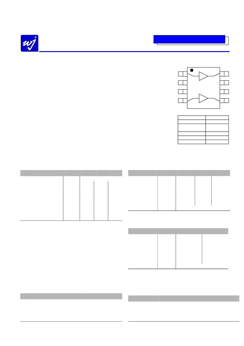
Functional Diagram
Function
Input (Amp 1)
Pin No.
1
2, 3, 6, 7,
Bottom Slug
4
5
8
Ground
Input (Amp 2)
Output (Amp 1)
Output (Amp 2)
Parameter
Test Frequency
Gain
Input Return Loss
(2)
Output Return Loss
Output IP3
(3)
Output P1dB
Noise Figure
Operating Current Range
Supply Voltage
Units
MHz
dB
dB
dB
dBm
dBm
dB
mA
V
Min
Typ
800
13.5
8
15
+41
+21
2.7
150
+5
Max
12.4
+37
120
180
1. Test conditions unless otherwise noted: T = 25 oC, Supply Voltage = +5 V, Frequency = 800 MHz,
50
Ω
System, tested on each single-ended amplifier (there are two amplifiers in an AH11 package)
2. S21 and S11 can be improved in the band of interest with some slight input tuning.
3. 3OIP measured with two tones at an output power of +5 dBm/tone separated by 10 MHz. The
suppression on the largest IM3 product is used to calculate the 3OIP using a 2:1 rule. Slight OIP3
degradation of about 2 dB is expected to occur at lower temperatures (from 25 oC to –40 oC).
Absolute Maximum Rating
Parameter
Operating Case Temperature
Storage Temperature
Supply Voltage
RF Input Power (continuous)
Junction Temperature
Rating
-40 to +85
°
C
-55 to +125
°
C
+6 V
4 dB above Input P1dB
+220
°
C
Operation of this device above any of these parameters may cause permanent damage.
Typical Performance
(Balanced Configuration)
Parameter
Frequency
S21
S11
S22
Output IP3
Noise Figure
Supply Bias
Test conditions: T = 25 oC, in a tuned application circuit (shown on page 2)
Typical Performance
(Dual P-P Configuration)
Units
MHz
dB
dB
dB
dBm
dB
Typical
1900
11.2
-14
-10
+44
4.2
+5 V @ 300 mA
900
12.2
-10
-18
+46
4.1
2100
10.6
-10
-10
+45
5.6
Parameter
Frequency
S21
S11
S22
Output IP3
Noise Figure
Supply bias
Test conditions: T = 25 oC, in a tuned application circuit (shown on pages 3 and 4)
Ordering Information
Part No.
Description
AH11-G
High Dynamic Range CATV Amplifier
(lead-free/green/RoHS-compliant SOIC-8 Package)
AH11BAL-PCB
0.6-2.1GHz Eval Board, Balanced Configuration
AH11PP900-PCB
0.9GHz Eval Board, Dual Push-Pull Configuration
AH11PP1900-PCB
1.9GHz Eval Board, Dual Push-Pull Configuration
Units
MHz
dB
dB
dB
dBm
dB
Typical
900
13.4
-19
-12
+48
3.4
1900
11.9
-19
-10
+48
3.7
+5 V @ 600 mA
1
2
3
4
8
7
6
5
相關(guān)PDF資料 |
PDF描述 |
|---|---|
| AH114-89G | Watt, High Linearity InGaP HBT Amplifier |
| AH114-89PCB1900 | Watt, High Linearity InGaP HBT Amplifier |
| AH114-89PCB2140 | Watt, High Linearity InGaP HBT Amplifier |
| AH114-89PCB900 | Watt, High Linearity InGaP HBT Amplifier |
| AH116-RFID | 1/2 Watt, High Linearity InGaP HBT Amplifier |
相關(guān)代理商/技術(shù)參數(shù) |
參數(shù)描述 |
|---|---|
| AH11PP1900-PCB | 功能描述:射頻開(kāi)發(fā)工具 1900MHz Push-Pull Eval Brd 12dB Gain RoHS:否 制造商:Taiyo Yuden 產(chǎn)品:Wireless Modules 類(lèi)型:Wireless Audio 工具用于評(píng)估:WYSAAVDX7 頻率: 工作電源電壓:3.4 V to 5.5 V |
| AH11PP900-PCB | 功能描述:射頻開(kāi)發(fā)工具 900MHz Push-Pull Eval Brd 13dB Gain RoHS:否 制造商:Taiyo Yuden 產(chǎn)品:Wireless Modules 類(lèi)型:Wireless Audio 工具用于評(píng)估:WYSAAVDX7 頻率: 工作電源電壓:3.4 V to 5.5 V |
| AH11TRG | 制造商:TriQuint Semiconductor 功能描述:GAIN BLOCK |
| AH1201GY | 制造商:Cooper Wiring Devices 功能描述: |
| AH1201LTVM | 制造商:Cooper Wiring Devices 功能描述: |
發(fā)布緊急采購(gòu),3分鐘左右您將得到回復(fù)。