- 您現(xiàn)在的位置:買賣IC網(wǎng) > PDF目錄362158 > AGC15 Fuse PDF資料下載
參數(shù)資料
| 型號: | AGC15 |
| 元件分類: | 保險(xiǎn)絲 |
| 英文描述: | Fuse |
| 中文描述: | 保險(xiǎn)絲 |
| 文件頁數(shù): | 1/2頁 |
| 文件大小: | 119K |
| 代理商: | AGC15 |
1-18-00
SB99210
Rev. A
Typical Voltage
Drop
Volts at
100% Rated
Current
.67
10.41
6.00
4.67
4.12
4.51
.89
2.88
4.59
2.67
.59
.37
.31
.35
.27
.28
.26
.31
.25
.22
.23
.23
.23
.19
.18
.20
.14
.12
.11
.12
Agency*
Approvals
Rated
Voltage
Interrupting
Rating
1
Pre-arcing
I
2
t (A
2
Sec)
Typical Total Clearing
3
I
2
t (A
2
Sec)
Rated
Current
o
§
o
§
¤o
¢
o
4fioo
¢
1
1¢
1
2
2¢
2
3
4
5
6
7
8
9
10
15 32V 32V
20
32V 32V
25 32V 32V
30
32V 32V
AC (Max.)
250V
250V
250V
250V
250V
250V
250V
250V
250V
250V
250V
250V
250V
250V
250V
250V
250V
250V
250V
250V
250V
250V
250V
250V
250V
250V
DC
6
(Max.)
250V
250V
250V
250V
250V
250V
250V
250V
250V
250V
250V
250V
250V
250V
250V
250V
250V
250V
250V
250V
250V
250V
250V
250V
250V
250V
AC
35A
35A
35A
35A
35A
35A
35A
35A
35A
35A
35A
35A
35A
100A
100A
100A
100A
100A
100A
200A
200A
200A
200A
200A
200A
200A
1000A 1000A
1000A 1000A
1000A 1000A
1000A 1000A
DC
6
35A
35A
35A
35A
35A
35A
35A
35A
35A
35A
35A
35A
35A
100A
100A
100A
100A
100A
100A
200A
200A
200A
200A
200A
200A
200A
AC
DC
6
4.09
AC
DC
6
7.94
2.60 ≈ 10
2.40 ≈ 10
5.50 ≈ 10
-4
6.50 ≈ 10
3.40 ≈ 10
1.01 ≈ 10
-4
-4
7.60 ≈ 10
4.77 ≈ 10
-5
-4
2.12 ≈ 10
1.27 ≈ 10
.003
.011
.013
.049
.051
.118
2.67
1.41
1.49
2.87
9.66
19.08
—
15.70
14.67
24.07
51.20
22.70
30.60
42.30
55.81
274.00
322.00
-4
-4
-4
-3
-3
.003
.008
.011
.015
.044
.091
.12
.28
.82
1.50
1.95
3.44
5.4
6.0
5.3
12.19
25.08
7.08
10.52
13.27
24.56
211.00
240.30
577.00
1241.00
2276.00
3812.00
.002
.007
.008
.014
.040
.072
.09
.24
.80
1.44
2.14
3.80
—
5.93
7.36
13.25
27.57
7.19
11.60
14.20
25.59
205.33
268.00
.69
.84
.74
.38
1.57
2.59
2.78
2.75
3.69
5.21
10.69
16.41
22.14
19.04
19.70
27.29
74.91
39.80
59.49
67.68
104.90
238.40
315.70
691.00
1450.00
2588.00
4098.00
*Approvals: U.L. Listed, Std. 248-14, Guide JDYX, File E19180; CSA Certification,
Class 1422-01, File 53787; AGC & AGC-V U.L. Recognized, Guide JDYX2, File E19180.
1. Interrupting ratings were measured at 70%-80% power factor on AC, and at a time constant
described in U.L. 198L.
2. Voltage drop was measured at 25
°
C ± 3
°
C ambient temperature at rated current.
3. I
2
t was measured at listed interrupting rating and rated voltage.
4. Interrupting rating for AGC ∞oo-10A @ 125V is 10,000A. Interrupting rating listed corresponds
to maximum rated voltage.
5. The AGC-10A fuse is self-certified for 32 Vdc at 1000 AIC.
6. Other available sizes include: ∞oo, oo, oo, ∞o, £, fi/oo, fi/ooo, £, /o, fl/o, °/o, 1¤/o,
1/o, 1fl/o, 1/¢, 1°/o, 3¤/o, 3, 4, 6¢, 7, 12 and 14.
7. 1-10A, U.L. Recognized for 125 Vdc and 500 AIC. Other DC ratings are self-certified.
U
U
C
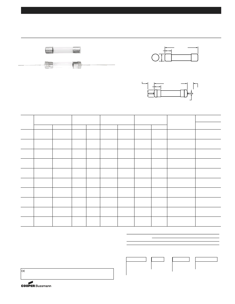
Electrical Characteristics
Fast-Acting Glass Fuses
AGC
AGC-V
For ¢∑ ≈ 1¢∑ (6.3mm ≈ 32mm)
Form No. AGC
Page 1 of 2
BIF Doc #2001
Bussmann
Packaging & Ordering Information:
Package Code
Blank
5 in
BK/
100 in
Product
Symbol
Lead
Blank -no lead
V-Axial lead
Rated Current
(See Table)
V
AGC
Catalog Symbol:
AGC (3AG)
Fast-Acting
*Agency Approvals:
U.L./CSA 248-14
Construction:
Glass Tube
Nickel-Plated Brass Endcaps
.25
0
6.35mm
.25
0
(
±
0.003)
6.35mm
1.25
0
(
±
0.031)
31.85mm
.266
0
6.76mm
o
–15 AMP: .032
0
.81mm
20–30 AMP: .040
0
1.02mm
1.292
0
±
.031
32.82mm
±
.79
1.500
0
38.10mm
(REF)
1.500
0
38.10mm
(REF)
(REF)
(REF)
Time-Current Characteristics
Rated
Current
o
-30
Percent of Rating
135%
60 min. (max)
110%
4 hrs. (min)
200%
120 sec. (max)
Dimensional Data
–
–
CE logo denotes compliance with European Union Low Voltage Directive
(50-1000 Vac, 75-1500 Vdc). Refer to BIF document #8002 or contact
Bussmann Application Engineering at 636-527-1270 for more information.
相關(guān)PDF資料 |
PDF描述 |
|---|---|
| AGC2 | Fuse |
| AGC20 | Fuse |
| AGC25 | Fuse |
| AGC3 | Fuse |
| AGC30 | Fuse |
相關(guān)代理商/技術(shù)參數(shù) |
參數(shù)描述 |
|---|---|
| AGC-15 | 功能描述:保險(xiǎn)絲 15 AMP 32V FAST ACTING RoHS:否 制造商:Littelfuse 產(chǎn)品:Surface Mount Fuses 電流額定值:0.5 A 電壓額定值:600 V 保險(xiǎn)絲類型:Fast Acting 保險(xiǎn)絲大小/組:Nano 尺寸:12.1 mm L x 4.5 mm W 安裝風(fēng)格: 端接類型:SMD/SMT 系列:485 |
| AGC-15/100 | 功能描述:保險(xiǎn)絲 BUSS SMALL DIMENSION FUSE FAST ACTING RoHS:否 制造商:Littelfuse 產(chǎn)品:Surface Mount Fuses 電流額定值:0.5 A 電壓額定值:600 V 保險(xiǎn)絲類型:Fast Acting 保險(xiǎn)絲大小/組:Nano 尺寸:12.1 mm L x 4.5 mm W 安裝風(fēng)格: 端接類型:SMD/SMT 系列:485 |
| AGC-15/100-R | 功能描述:保險(xiǎn)絲 .15 AMP 250V FAST ACTING RoHS:否 制造商:Littelfuse 產(chǎn)品:Surface Mount Fuses 電流額定值:0.5 A 電壓額定值:600 V 保險(xiǎn)絲類型:Fast Acting 保險(xiǎn)絲大小/組:Nano 尺寸:12.1 mm L x 4.5 mm W 安裝風(fēng)格: 端接類型:SMD/SMT 系列:485 |
| AGC-1-50 | 功能描述:保險(xiǎn)絲 SMALL DIMENSION FUSE RoHS:否 制造商:Littelfuse 產(chǎn)品:Surface Mount Fuses 電流額定值:0.5 A 電壓額定值:600 V 保險(xiǎn)絲類型:Fast Acting 保險(xiǎn)絲大小/組:Nano 尺寸:12.1 mm L x 4.5 mm W 安裝風(fēng)格: 端接類型:SMD/SMT 系列:485 |
| AGC-1-50-R | 功能描述:保險(xiǎn)絲 RoHS:否 制造商:Littelfuse 產(chǎn)品:Surface Mount Fuses 電流額定值:0.5 A 電壓額定值:600 V 保險(xiǎn)絲類型:Fast Acting 保險(xiǎn)絲大小/組:Nano 尺寸:12.1 mm L x 4.5 mm W 安裝風(fēng)格: 端接類型:SMD/SMT 系列:485 |
發(fā)布緊急采購,3分鐘左右您將得到回復(fù)。