- 您現(xiàn)在的位置:買賣IC網(wǎng) > PDF目錄223321 > AEE00C24 1-OUTPUT 10 W DC-DC REG PWR SUPPLY MODULE PDF資料下載
參數(shù)資料
| 型號: | AEE00C24 |
| 元件分類: | 電源模塊 |
| 英文描述: | 1-OUTPUT 10 W DC-DC REG PWR SUPPLY MODULE |
| 封裝: | 2 X 1 INCH, MODULE-4 |
| 文件頁數(shù): | 8/22頁 |
| 文件大小: | 301K |
| 代理商: | AEE00C24 |
A
A
A E
E
E E
E
E 0
0
0 1
1
1 L
L
L 2
2
2 4
4
4 ////L
L
L 4
4
4 8
8
8 D
D
D C
C
C --D
D
D C
C
C C
C
C o
o
o n
n
n v
v
v e
e
e rrrrtttte
e
e rrrrs
s
1
1 8
8
8 --3
3
3 6
6
6 V
V
V d
d
d c
c
c a
a
a n
n
n d
d
d 3
3
3 6
6
6 --7
7
7 2
2
2 V
V
V d
d
d c
c
c IIIIn
n
n p
p
p u
u
u tttt,,,, 1
1
1 0
0
0 W
W
Wa
a
a tttttttt S
S
S iiiin
n
n g
g
g lllle
e
e O
O
O u
u
u ttttp
p
p u
u
u tttt
-16-
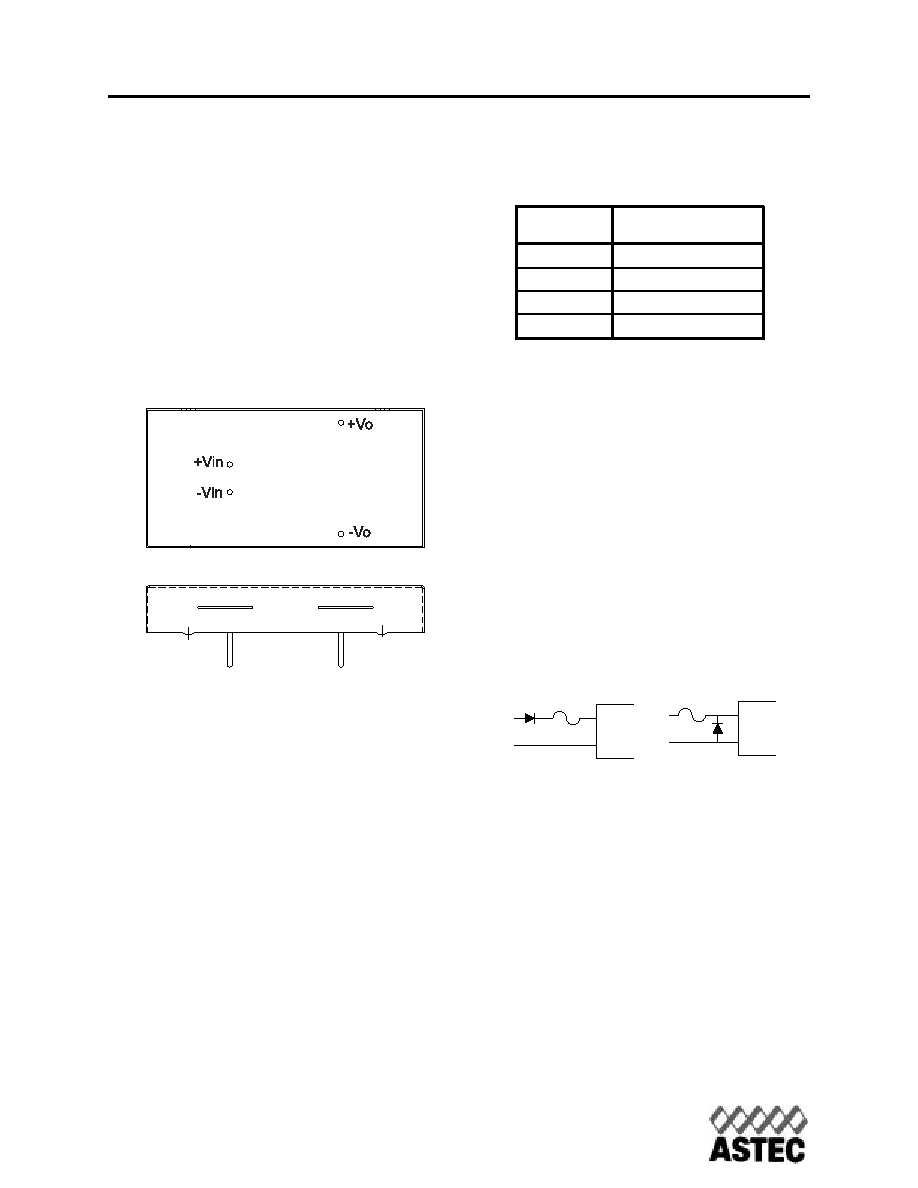
Pin Location
The +Vin and -Vin input connection pins are
located as shown in Figure 1. AEE converters
have a 2:1 input voltage range of 18-36V or 36-
72V.
Care should be taken to avoid applying
reverse polarity to the input which can dam-
age the converter.
Input Characteristic
Fusing
The AEE series power module has no inter-
nal fuse. An external fuse must always be
employed!
To meet international safety requirements, a
250 Volt rated fuse should be used. If one of the
input lines is connected to chassis ground, then
the fuse must be placed in the other input line.
Standard safety agency regulations require
input fusing. Recommended fuse ratings for the
AEE series are shown in Table 1.
T
Table 1
able 1
Input Reverse V
Input Reverse Voltage Protection
oltage Protection
Under installation and cabling conditions where
reverse polarity across the input may occur,
reverse polarity protection is recommended.
Protection can easily be provided as shown in
Figure 2. In both cases the diode rating is rated
for 2A/100V.
Placing the diode across the inputs rather
than in-line with the input offers an advan-
tage in that the diode only conducts in a
reverse polarity condition, which increases
circuit efficiency and thermal performance.
Input Filter
Input filters are included in the converters to
help achieve standard system emissions certifi-
cations. Some users however, may find that
additional input filtering is necessary. The AEE
series has an internal switching frequency of
330 kHz so a high frequency capacitor mount-
ed close to the input terminals produces the
best results. To reduce reflected noise, a
capacitor can be added across the input as
shown in Figure 3, forming a
π filter. A
Fig.1 Pin Location
Series
Fuse Rating
24Vin
2A
48Vin
1A
+Vin
-Vin
+Vin
-Vin
Fig.2 Reverse Polarity Protection Circuits
www.astec.com
USA
Europe
Asia
TEL: 1-760-930-4600
44-(0)1384-842-211
852-2437-9662
FAX: 1-760-930-0698
44-(0)1384-843-355
852-2402-4426
相關(guān)PDF資料 |
PDF描述 |
|---|---|
| AEE01B36-L | 1-OUTPUT 15 W DC-DC REG PWR SUPPLY MODULE |
| AFBR-2010S | FIBER OPTIC RECEIVER, 630-685nm, 50Mbps, THROUGH HOLE MOUNT |
| AFBR-2010 | FIBER OPTIC RECEIVER, 630-685nm, 50Mbps, THROUGH HOLE MOUNT |
| AFBR-57D7APZ | FIBER OPTIC TRANSCEIVER, 840-860nm, 8500Mbps(Tx), 8500Mbps(Rx), SURFACE MOUNT, LC CONNECTOR |
| AFBR-57J5APZ | FIBER OPTIC TRANSCEIVER, 830-860nm, 24576Mbps(Tx), 24576Mbps(Rx), BOARD/PANEL MOUNT, LC CONNECTOR |
相關(guān)代理商/技術(shù)參數(shù) |
參數(shù)描述 |
|---|---|
| AEE00C24L | 制造商:Johnson Components 功能描述:24V-15V 10W 1 X 2 X 0.35 H |
| AEE00C48 | 功能描述:DC/DC轉(zhuǎn)換器 CONV DC-DC 10W 24VIN RoHS:否 制造商:Murata 產(chǎn)品: 輸出功率: 輸入電壓范圍:3.6 V to 5.5 V 輸入電壓(標(biāo)稱): 輸出端數(shù)量:1 輸出電壓(通道 1):3.3 V 輸出電流(通道 1):600 mA 輸出電壓(通道 2): 輸出電流(通道 2): 安裝風(fēng)格:SMD/SMT 封裝 / 箱體尺寸: |
| AEE00C48-L | 制造商:Emerson Network Power - Embedded Power 功能描述:- Trays |
| AEE00CC12 | 制造商:未知廠家 制造商全稱:未知廠家 功能描述:DC to DC Converter |
| AEE00CC12-1 | 制造商:未知廠家 制造商全稱:未知廠家 功能描述:DC to DC Converter |
發(fā)布緊急采購,3分鐘左右您將得到回復(fù)。