- 您現(xiàn)在的位置:買賣IC網(wǎng) > PDF目錄374047 > ADV7190 (Analog Devices, Inc.) Video Encoder with Six 10-Bit DACs and Video Encoder with Six DAC Outputs PDF資料下載
參數(shù)資料
| 型號(hào): | ADV7190 |
| 廠商: | Analog Devices, Inc. |
| 英文描述: | Video Encoder with Six 10-Bit DACs and Video Encoder with Six DAC Outputs |
| 中文描述: | 視頻編碼器與六10位DAC和DAC的輸出6視頻編碼器 |
| 文件頁(yè)數(shù): | 41/69頁(yè) |
| 文件大?。?/td> | 628K |
| 代理商: | ADV7190 |
第1頁(yè)第2頁(yè)第3頁(yè)第4頁(yè)第5頁(yè)第6頁(yè)第7頁(yè)第8頁(yè)第9頁(yè)第10頁(yè)第11頁(yè)第12頁(yè)第13頁(yè)第14頁(yè)第15頁(yè)第16頁(yè)第17頁(yè)第18頁(yè)第19頁(yè)第20頁(yè)第21頁(yè)第22頁(yè)第23頁(yè)第24頁(yè)第25頁(yè)第26頁(yè)第27頁(yè)第28頁(yè)第29頁(yè)第30頁(yè)第31頁(yè)第32頁(yè)第33頁(yè)第34頁(yè)第35頁(yè)第36頁(yè)第37頁(yè)第38頁(yè)第39頁(yè)第40頁(yè)當(dāng)前第41頁(yè)第42頁(yè)第43頁(yè)第44頁(yè)第45頁(yè)第46頁(yè)第47頁(yè)第48頁(yè)第49頁(yè)第50頁(yè)第51頁(yè)第52頁(yè)第53頁(yè)第54頁(yè)第55頁(yè)第56頁(yè)第57頁(yè)第58頁(yè)第59頁(yè)第60頁(yè)第61頁(yè)第62頁(yè)第63頁(yè)第64頁(yè)第65頁(yè)第66頁(yè)第67頁(yè)第68頁(yè)第69頁(yè)
ADV7190/ADV7191
–41–
REV. 0
DNR2 BIT DESCRIPTION
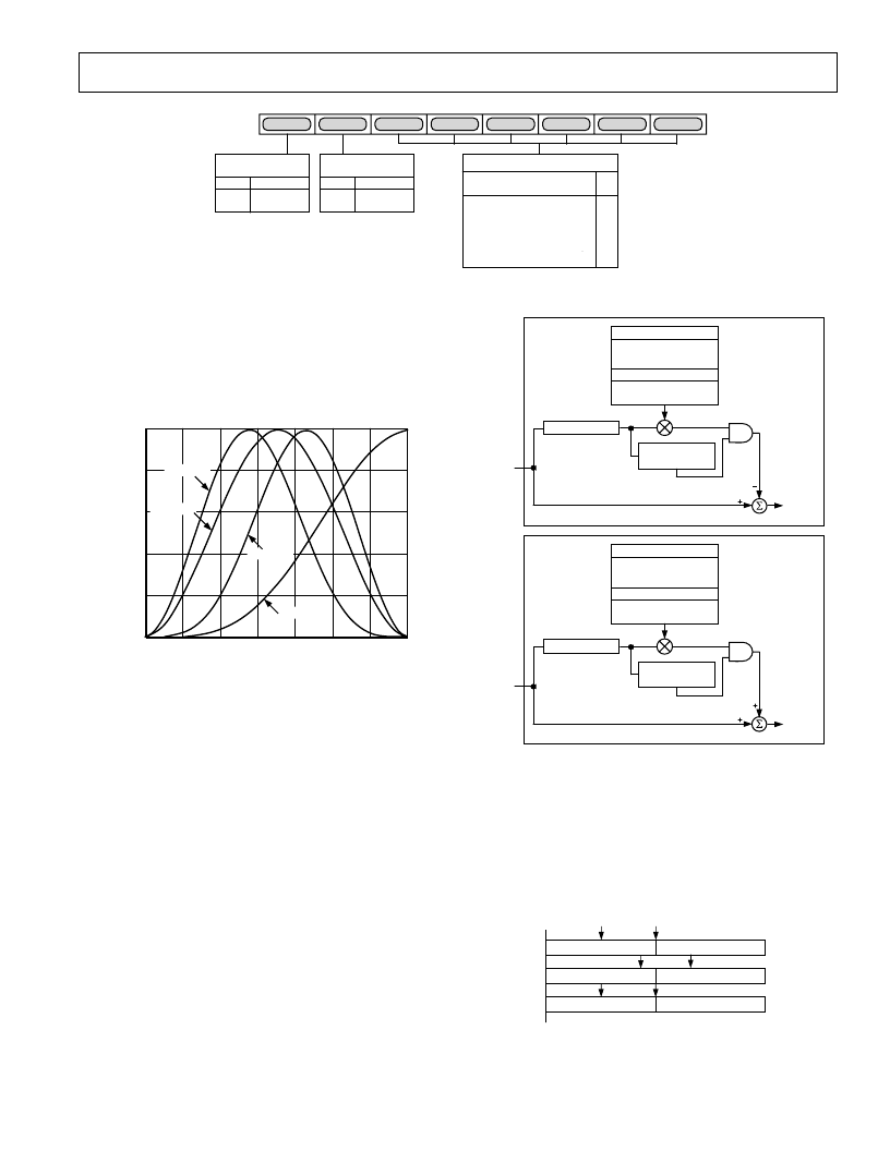
DNR Input Select (DNR20–DNR22)
Three bits are assigned to select the
fi
lter which is applied to the
incoming Y data. The signal which lies in the passband of the
selected
fi
lter is the signal which will be DNR processed. Figure
81 shows the
fi
lter responses selectable with this control.
FREQUENCY
–
MHz
1
0.4
0.6
0.2
0
1
M
–
2
3
4
6
5
0.8
0
FILTER D
FILTER C
FILTER A
FILTER B
Figure 81. Filter Response of Filters Selectable
DNR Mode Control (DNR23)
This bit controls the DNR mode selected. A Logic 0 selects
DNR mode, a Logic 1 selects DNR Sharpness mode.
DNR works on the principle of de
fi
ning low amplitude, high-
frequency signals as probable noise and subtracting this noise
from the original signal.
In DNR mode, it is possible to subtract a fraction of the signal
which lies below the set threshold, assumed to be noise, from
the original signal. The threshold is set in DNR Register 1.
When DNR Sharpness mode is enabled it is possible to add a
fraction of the signal that lies above the set threshold to the
original signal, since this data is assumed to be valid data and
not noise. The overall effect being that the signal will be boosted
(similar to using Extended SSAF Filter).
FILTER OUTPUT
< THRESHOLD
GAIN CONTROL
BLOCK SIZE CONTROL
BORDER AREA
BLOCK OFFSET
GAIN
CORING GAIN DATA
CORING GAIN BORDER
FILTER BLOCK
FILTER OUTPUT
> THRESHOLD
DNR
OUT
MAIN SIGNAL PATH
Y DATA
INPUT
NOISE SIGNAL PATH
SUBTRACT
SIGNAL IN
THRESHOLD
RANGE
FROM
ORIGINAL
SIGNAL
DNR
MODE
FILTER OUTPUT
> THRESHOLD
GAIN CONTROL
BLOCK SIZE CONTROL
BORDER AREA
BLOCK OFFSET
GAIN
CORING GAIN DATA
CORING GAIN BORDER
FILTER BLOCK
FILTER OUTPUT
< THRESHOLD
DNR
OUT
MAIN SIGNAL PATH
Y DATA
INPUT
NOISE SIGNAL PATH
ADD
SIGNAL
ABOVE
THRESHOLD
RANGE
TO
ORIGINAL
SIGNAL
DNR
SHARPNESS
MODE
Figure 82. Block Diagram for DNR Mode and DNR Sharp-
ness Mode
Block Offset (DNR24–DNR27)
Four bits are assigned to this control which allows a shift of the
data block of 15 pixels maximum. Consider the coring gain po-
sitions
fi
xed. The block offset shifts the data in steps of one pixel
such that the border coring gain factors can be applied at the same
position regardless of variations in input timing of the data.
O X X X X X X O O X X X X X X O
APPLY DATA
CORING GAIN
APPLY BORDER
CORING GAIN
OFFSET
CAUSED BY
VARIATIONS IN
INPUT TIMING
DNR27
–
DNR24
= 01 HEX
O X X X X X X O O X X X X X X O
O X X X X X X O O X X X X X X O
Figure 83. DNR27–DNR24, Block Offset Control
DNR17
DNR16
DNR15
DNR14
DNR13
DNR12
DNR11
DNR10
DNR THRESHOLD
DNR DNR DNR DNR DNR DNR
15 14 13 12 11 10
0 0
0
0
0
0
1
1
1
1
1
1
0
0
1
1
0
0
1
1
0
1
0
1
0
1
62
63
0
1
2 PIXELS
4 PIXELS
DNR16
BORDER AREA
0
1
8 PIXELS
16 PIXELS
DNR17
BLOCK SIZE
CONTROL
Figure 80. DNR Register 1
相關(guān)PDF資料 |
PDF描述 |
|---|---|
| ADV7192KST | Video Encoder with Six 10-Bit DACs, 54 MHz Oversampling and Progressive Scan Inputs |
| ADV7192 | Video Encoder with Six 10-Bit DACs, 54 MHz Oversampling and Progressive Scan Inputs |
| ADV7194KST | Professional Extended-10⑩ Video Encoder with 54 MHz Oversampling |
| ADV7194 | Professional Extended-10⑩ Video Encoder with 54 MHz Oversampling |
| ADV7202 | Simultaneous Sampling Video Rate Codec |
相關(guān)代理商/技術(shù)參數(shù) |
參數(shù)描述 |
|---|---|
| ADV7190KST | 制造商:AD 制造商全稱:Analog Devices 功能描述:Video Encoder with Six 10-Bit DACs and Video Encoder with Six DAC Outputs |
| ADV7190KSTZ | 制造商:Analog Devices 功能描述:Video Encoder 6DAC 10-Bit 64-Pin LQFP |
| ADV7191 | 制造商:AD 制造商全稱:Analog Devices 功能描述:Video Encoder with Six 10-Bit DACs and Video Encoder with Six DAC Outputs |
| ADV7191KST | 制造商:Analog Devices 功能描述:Video Encoder 6DAC 10-Bit 64-Pin LQFP 制造商:Rochester Electronics LLC 功能描述:54M 4X STD DEF ENCODER NON-MACRO I.C. - Tape and Reel |
| ADV7191KSTZ | 制造商:Analog Devices 功能描述:Video Encoder 6DAC 10-Bit 64-Pin LQFP 制造商:Analog Devices 功能描述:IC VIDEO ENCODER |
發(fā)布緊急采購(gòu),3分鐘左右您將得到回復(fù)。